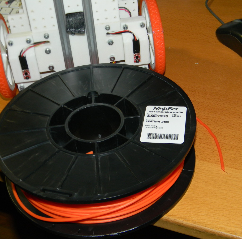
After having printed a lot with ABS and PLA, finally decided to get a roll of Ninjaflex filament for testing on my Prusa Version 1. I was expecting that given this filament’s flexible characteristics I would have to do many adjustments to the printing parameters however I was surprised at how easy it was to print almost perfectly since the first attempt.
I had read that one of the main difficulties when printing Ninjaflex with a Wade’s type extruder was that the filament could bend easily when being pushed and get stuck in the empty gap between the Hobbed Bolt and the small PTFE Tubing of the J-Head. This problem is more common with the 1.75 mm filament. I have seen some youtube videos where people has resolved this issue by extending the PTFE tube (or Bowden tube) up as to shorten the empty space between it at the Hobbed bolt.
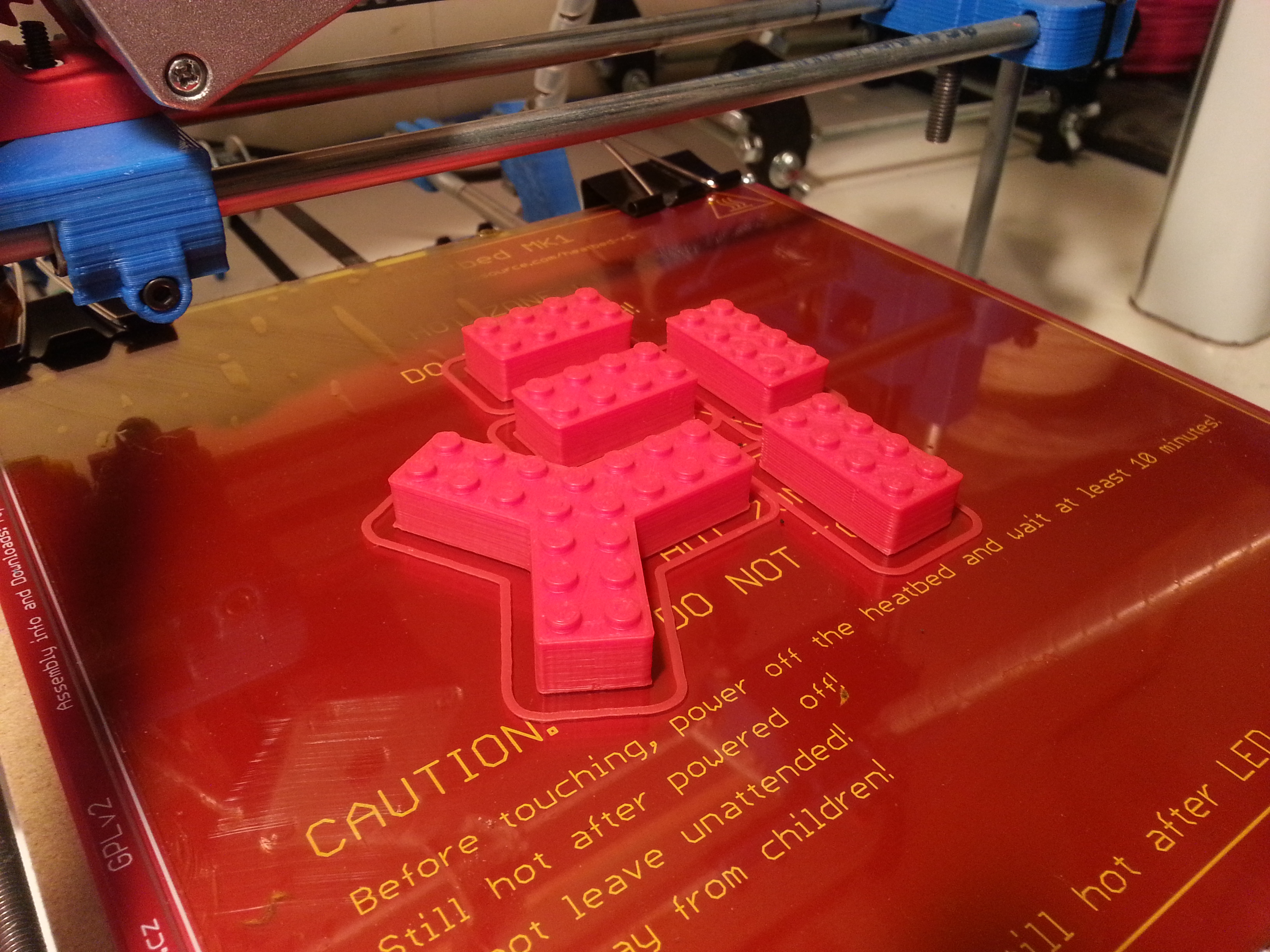
I am using 3 (2.85) mm filament which is less susceptible of having the above issue, however I did encounter this problem twice when printing multiple parts in the bed at the same time. It appears that the excessive use of retracts, when printing multiple independent parts, causes the filament to weaken and bend to a point where it just gets stuck.
That said, everything else worked perfectly. This material prints very well: it adheres to the glass much better than PLA, layers fuse together nicely, finish is very smooth and shinny and the parts are incredible strong.
Printing Parameters used:
Extruder Temperature: 215 C
Bed Temperature: 50 C First Layer, 40 C Other Layers
Auto Cooling Enabled (in Slic3r)
Speed 30 mm/s
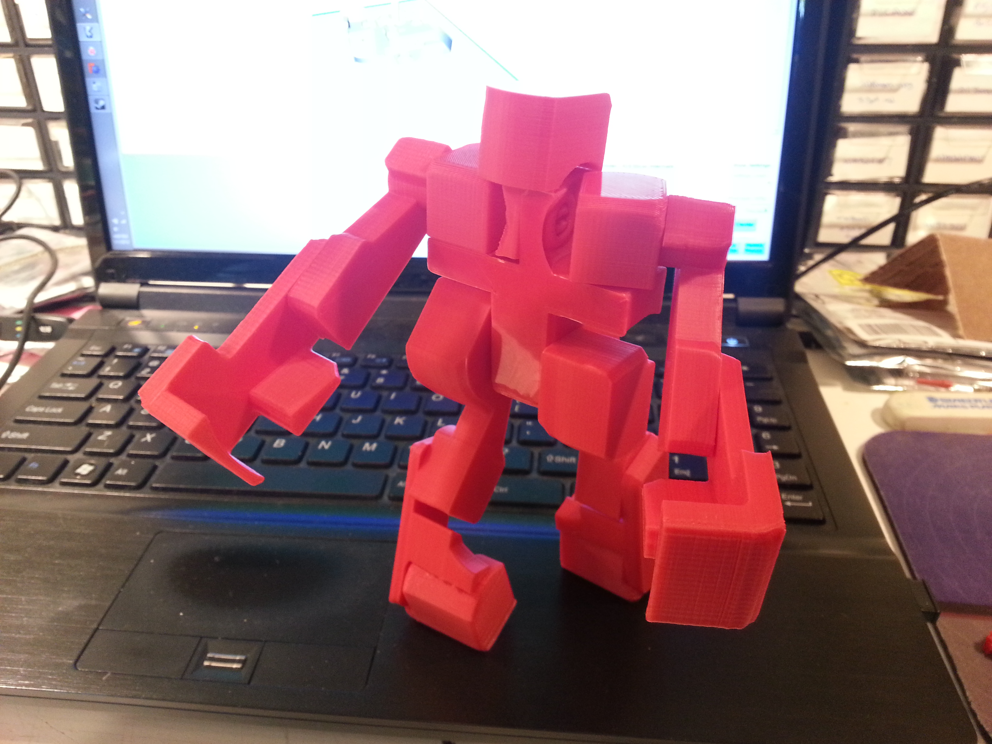
For testing I printed a set of all-terrain tires for my 3d Printed Multi Purpose robot. The caster wheel tire was printed with 50% infill.
The main tires were printed with 30% infill.
The robot with its new set of tires.
Ninjaflex is a great product and being able to print flexible parts greatly expands the capabilities of any 3d Printer.
After a long hiatus of my Robotics activities I am starting a new project: A Chess Playing Robot.
As a logical step up of the Tic Tac Toe Playing Robotic Arm I built some years ago I have started building a Chess Playing Robot. The idea is to build not only a Robot Arm that play chess against a human but to add some other components to make the chess playing experience against a machine less dry and boring.
In addition to the Arm, the plan is to add an animatronic face of some sort for the robotic opponent. This face should mimic some behaviors of a real opponent, like tracking with its eyes the pieces being played and to express emotions like concentration when planning moves, happiness when winning and preoccupation when loosing.
Another component will consist of control levers that the human player can use to adjust the robot’s playing level and style on the fly and at any time during the game. For example if after the opening the human player feels that the robot opponent level is to high or to low then using the levers the robot’s level could be adjusted as desired.
There are many technical aspects that will need to be worked out at due time, like which method of chess piece detection will be used, will the robot arm use inverse kinematics or preprogrammed positions, which chess engine and computing platform to use, etc. but to start I will be concentrating first in building a strong and reliable robot arm capable of grabbing and manipulating any standard chess piece in a standard tournament size board.
The robotic arm will have 5 degree of freedom plus a gripper. I am starting the design from the end actuator (the gripper) and continuing with the wrist roll wrist pitch, elbow, shoulder swivel and arm sweep. By starting from the actuator I can evaluate at each step how much torque I need for each subsequent joint. This is important as this time the robot will not be constructed with just servos, it will have servos only for the gripper and wrist and dc motors with encoders for the elbow and shoulder.
For the gripper, after evaluating different mechanisms, like gears and rack and pinion, to convert the servo rotation action to linear action (for three fingers separated at 120 degrees) I settled for this simple design that seems to work very well as the gripper action is fast and the gripping force is strong enough to hold any standard chess piece even if it grabs it off centered or at different height.
The gripper uses one Hobbyking TurnigyTG9e Analog Micro Servo with 1.5kg/cm (4.8V) of Torque. All parts were 3D printed in PLA and assembled with M2.5 screws.
Just a quick video showing how I depanelize PCBs. I typically buy PCBs from SeeedStudio or iTeadStudio and it makes sense to use the 10cm by 10cm board size and jam more than one PCB into that area. Diptrace (my schematic/PCB weapon of choice) makes it easy to panelize multiple designs, but its relatively easy in Eagle as well as others.
The CNC machine makes it easy to separate the boards out when I get them back. The same could be done with a bandsaw if that is what you have at hand. Basically I dump a DXF out from the PCB with the board outline and the 2mm silkscreen lines that I draw on the PCB to separate the various boards. Depending on whether I want something more fancy, I either bring that into QCAD (fantastic 2D drawing tool) to add goodies or straight into CamBam (amazing CAM tool for CNC).
I first get CamBam to make a pocket for the PCB so that I can align the PCBs the same for all 10 boards. I then create an engraving path along all the board separation lines. I’m a chicken so I always do two cuts, 35mil deep each. I use a 2mm 3-flute endmill and 12 inches per minute as a feedrate when cutting PCBs. My spindle speed is somewhere around 3200RPM if I recall correctly.
I use carpet tape to hold the PCBs in place in the pocket I cut and its off to the races. A shop-vac takes care of the dust.
I spent the weekend bringing one of those boards up… a 32 channel servo controller. More on that to come.
One of the big reasons to get the K40-III 40W engraving laser was to make stencils for PCBs. When I first got the machine, I ebay’d some 5mil laser transparencies as it sounded like some people had success with that. I really didn’t know what to expect, but I thought perhaps the best way would be to run with just enough power to burn through the plastic in order to minimize melting the edges. It worked ok, but was not very pretty. If I went slow enough to run the laser at minimum power, it would melt the edges. If I sped up, it wouldn’t cut entirely. So I put it on the backburner at that time. Soon thereafter I tore out the engraving table and put in some honeycomb material from LightObject on a fixed base and got to business with lots of wood cutting.
This week I finally had a chance to get back to figuring out the stencils. I ordered a roll of 3mil mylar from McMaster-Carr because I had an idea that thinner material might be better for the smaller surface mount stuff that I play with. Once it showed up, I got to work.
After fighting with MoshiDraw (software and controller that comes with many of these low cost lasers) and figuring out what the various engraving settings did, I starting running at different speeds to see what was best. I already knew that my initial settings were the wrong way to go… higher power and speed is better according to general consensus on the internet at large. So I started with my power at 15mA (works out to about 30W I think) and tried various speeds ranging from 16cm/s to 24cm/s. I also varied the amount I shrink the paste openings by, the laser step-over (called step for the x and distance for the y), as well as something called ‘addsize’ in Moshidraw. Haven’t figured out what that last one does yet… It defaults to 2 and I’ve settled on 0 just so it doesn’t muck things up.
Turns out that 18cm/s, a 5mil shrink on the pads, 15mA power, 0.1mm (or better yet 0.05mm if you have patience) step in x, distance 1 line, and having an open area under the mylar sheet works pretty damn well.
I’ll be soldering with it tomorrow and will report back the results.
I got tired of a fixed z-height on the laser and kicked around a couple of ideas of how to build my own stepper controlled version. Before I got started, a power table at LightObject came in stock for pre-ordering at the start of February. The classic time-versus-money argument. I decided to spend the money. It arrived today and it is beautiful. Sadly I won’t be able to put it in this weekend (busy with the soldering mentioned above), so that’s a project for next weekend. A 70L/min aquarium pump also arrived so I’ll have to rig up an air assist for it also. The lens gets too smoky when cutting otherwise.
Speaking of next weekend, there is a 3D Print-a-thon happening at ArtEngine here in Ottawa on March 2nd, 2013 to celebrate the arrival of their Ultimakers (which are likely being bolted together as I write this). They put out the call for people with printers to come and show off, so I’ll have my Prusa and Printrbot Jr there.
The Printrbot Jr. has been working like a champ. When I last posted I was struggling with getting the PLA to stick. After ordering some blank PCB material and some engraving bits for my CNC to make a hot-bed, I discovered that if I simply replace the blue 3M painters tape between each print, it works perfectly. No fuss, no muss. Dang… all that wasted time with sugar mixes, hotair guns, etc… I do rub the tape with a bit of acetone after putting on the tape… I have a crazy idea that it smooths out the wax on the tape and makes for a nicer finish. I could just be dreaming.
Anyhow, the Printrbot Jr. is working great. I think my longest print to date was two 3 hours prints, back to back, and the Jr. did it without breaking a sweat.
And the Prusa is back up and running thanks to Voxel Factory and their speedy delivery of a replacement J-Head. The J-Head puts my old Arcol V3 to shame I think. It has printed everything I’ve thrown at it. I highly recommend using the J-Head.
Well, I’ve had the Printrbot Jr. up and running for over a month now. Maybe more. Had plenty of help putting it together. The design is quite nice and appears to be well thought out. The kids had little trouble following along and putting the pieces together.
The instructions at the time consisted only of a youtube video but was decent enough to figure out where it all went. The only catch was a belt threaded through differently than the firmware expected but that was easy to sort out after the fact by swapping a few wires on the stepper connector.
I spent a bunch of time figuring out how to run the wires and make it all pretty. The wires all come with connectors on them ready to plug in but that leads to a bit of a bundle of wires to jam into the small electronics compartment. I cut all the wires to length and replaced the connectors. That resulted in a much less busy enclosure and might aid in cooling hopefully.
I’ve been having troubles getting the PLA to stick to my blue 3M tape bed. As the PLA squirts from the nozzle, it just didn’t appear to stick well and tended to curve up with the nozzle. I tried different print heights and speeds. With a little patience it was possible to get a smaller print done. Quality is pretty nice once the first layer sticks down.
The PLA has more trouble with overhangs than I’m used to with ABS. I tried printing a Pikachu that I’ve done before with ABS. The model has two small hands which overhang out the front. With ABS the first layer was ugly but the next one worked nicely and the print was beautiful. The PLA had much more trouble. I can see that a fan will come in very handy.
This past weekend I did a bit of poking around and discovered that the plywood bed is curved across itself diagonally so all my efforts to level the bed at the corners had been wasted mostly. The center where I do the printing was raised so all the PLA was getting smooshed in that area. If I dropped the bed a bit to accommodate it, then anything not at the center of the bed wouldn’t stick very well.
So I took the bed off and flipped it over so it curved downwards instead. I then cut a piece of glass to the right size and clipped it on the bed. That gave a nice flat surface to print on.
It didn’t help my sticking issue though. Apparently I was fighting 2 battles and hadn’t known it. I decided that I likely needed to build a small heated bed for the Printrbot Jr. before pushing it into heavier use. I put that onto the list of things to do and went back to my Prusa for the what I figured was the time being.
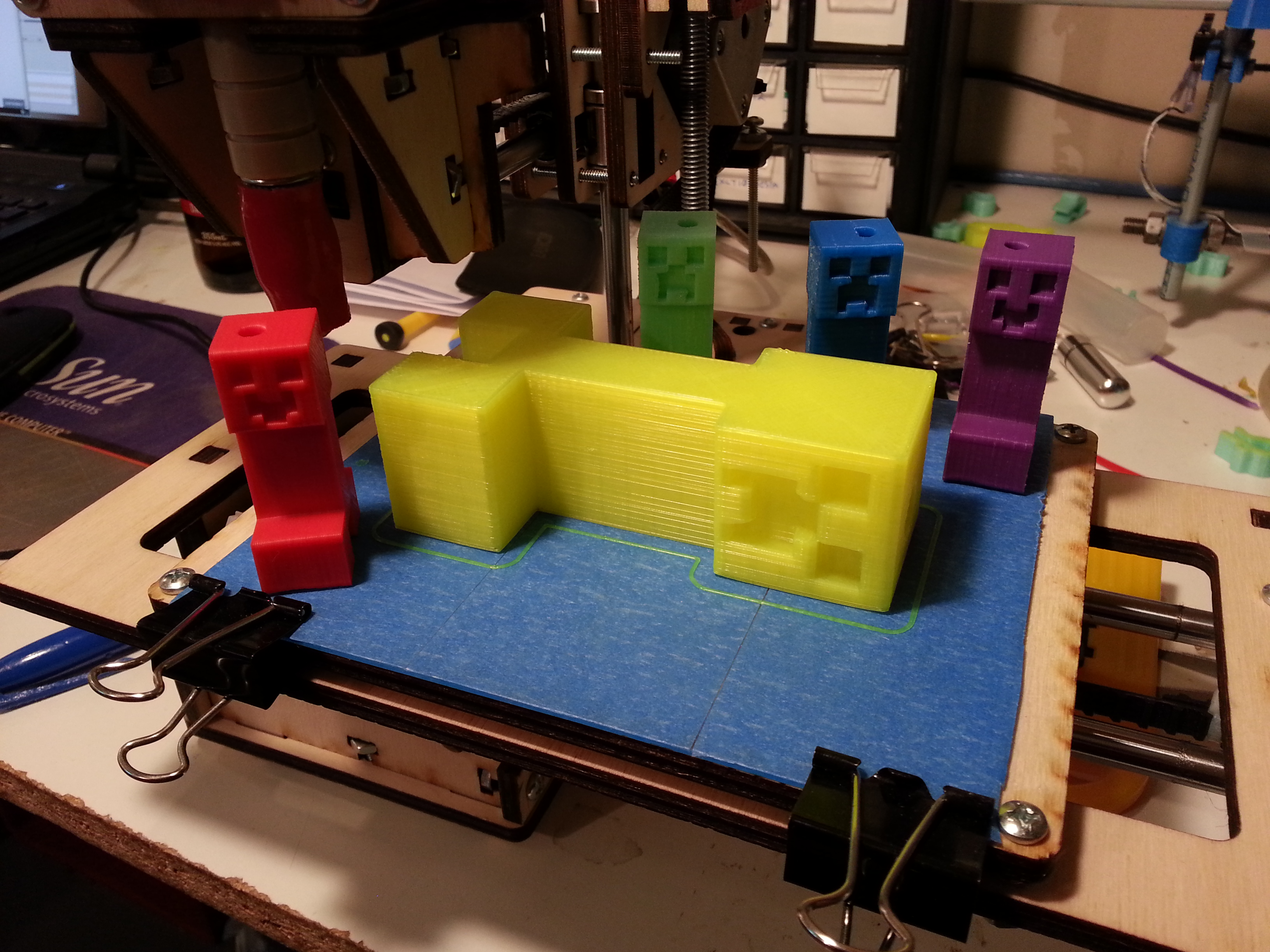
I needed to print out a bunch of glow in the dark Minecraft Creepers which required my ABS anyhow. After about 3 hours of printing I started getting jams. I blamed crud in the filament given that I’ve been using cheap stuff and forged ahead. The problem kept recurring. I ran out of time that night and came back to it the next day. Started printing again and all is good. Then about 2 or 3 hours in, the jamming starts again. I tweaked settings, played with various things and no luck. And then it happened…. total jam. Couldn’t even force the filament through by hand. Uh oh… more serious.
I’ve been using an Arcol V3 hotend for a long while now and have been pretty happy with it. Its a bit of a pain to disassemble though. Its an early version and doesn’t haven’t any of the nicer features like flats on the nozzle to help pull it apart.
So I pulled the nozzle off my printer and set about pull it it all apart to get whatever was jamming it out. Everything came apart pretty nicely aside from the nozzle from the heater block body. I found a gap between the nozzle and the PTFE tube where ABS had been collecting. There was also some scorching on the Peek where it screws into the nozzle. It looked like a small bit of ABS material might have started to squeezed out these threads. Likely from all the pressure caused by the plug.
I heated up the extruder and set about trying to separate the nozzle and heater block. It unscrewed about half way and then jammed. Couldn’t go forward, couldn’t go back. A more patient person would have let the whole thing just sit in acetone for the night to see if that loosened things up. I on the other hand pulled out the vice grip and started twisting. All that accomplished was jamming it a little bit more and then turning the round nozzle body into an oval. No chance of getting a nice seal with the peek portion every again.
So… two choices at this point. Reorder another nozzle from Arcol, wait 3 weeks or so reassemble and hope that the gap between the PTFE and peek doesn’t cause any issues later, or go to a different hot-end design. I love change so I started looking at new hotends. 😉 The Arcol V4 looks awesome but is pricey. Eckertech has a cool looking hotend. I’ve been using their hobbed bolt, their Prusa V1 plastics and their 3mm filament for some things and I know they are a quality operation. The only catch was the active cooling requirement and the fan that would hang off the side. It meant replacing my carriage, running more power down there and finding room for the fan.
In the end, I went with the J-Head Mk V from Reifsnyder Precision Works. The version 4 has been used quite a bit by others and has a good reputation. The version 5 is more of the same but smaller and tweaks. Who could resist. I’ve been looking for an excuse to try it out. Of course, the catch is that they are out of stock at Hot-ends and it would have taken a few weeks anyhow.
Voxel Factory to the rescue! I’ve had my eye on them for a while. The filament prices are pretty good, especially if I was in Montreal and could just pick it up. They have good prices on electronics and other goodies too. And they have the hot ends that I need. Or so I hope… they don’t display stock levels on their website. I ordered two of them so I’m hoping that they ship out today and I’ll have them next week. Fingers crossed. [update from comments below… in stock and shipped today!]
So, how does the Printrbot save the day? Well, my extruder body is custom printed just for the Arcol head. It has a different mounting system than a normal hot-end. I’ve also done some tweaking on the extruder itself also to squeeze the stepper motor closer and give me a little extra room on my X axis. So I needed a new extruder printed which would have the j-head mount. Piece of cake… fired up OpenSCAD, added a hole and screw mounts for the j-head and dumped out a new STL.
Now to sort out the print problems with the Jr. Tried slowing the first layer down to 5mm/s and then 3mm/s. Sticks better but not good enough. Tried with a raft. No good. I finally remembered that some people were using hair spray or sugar water to make it stick. No hair spray around but sugar water was easy to mix up. I dabbed it on the 3M tape and then hit it with the heat gun to dry up the water and leave behind the stickiness. Then it occurred to me… just use the heat gun and get the bed warm for the first layer.
So I did. Well… sugar water, heat-gun and raft all to make sure it worked. Stuck down like a charm. The raft wasn’t necessary as it turned out. I’m not convinced that the sugar water did much either. I think it was all heat gun awesomeness.
So, new extruder body ready to go. Just need to get the new hot-end and I’m back in action. Handy to have a spare printer when one printer goes down!
Now to start laying out a custom heated PCB bed for the Printrbot Jr. Looks like it will save me some trouble later on!
Its been a fun week… first the laser and now the Printrbot Jr. arrived last night!
We weren’t going to build the printer until this weekend, but decided to take a look at all the pretty wood pieces. Printrbot has a nice diagram (http://printrbot.com/wp-content/uploads/2012/10/Parts-Diagram-JRv18.pdf) showing all the laser cut pieces so we laid it all out just to make sure we had them all.
Dang! We are missing part 326!!!! Printrbot doesn’t have the design files up for this printer yet, so I posted on the Printrbot forums to see if anyone had one of these parts kicking around that they could measure up for me. I also put in a support request on the Printrbot website saying that I had a missing part.
They shipped out a replacement part gratis about 30 minutes later! Wow. Awesome service. No response on the forum from other users though. Just not enough Jr. printers out in the wild yet I guess.
But who the heck wants to wait a week for that part??? So I did some googling and found a nice picture of the missing part.
Looks easy enough. Its just holding two piece of wood together which trap a nut on the z-axis drive. The outside dimensions aren’t critical, so just a matter of getting the inside right.
I took the pdf from their website and imported it into CorelDraw. I then took a few measurements of the parts that will plug into this and resized the pdf of part 326 up to what I figured I needed.
I then fired up the frikkin’ laser! Well…. actually I did a test cut on the plywood to find a nice speed and power level which would blast through some 1/4″ plywood in one cut. After a couple of attempts, I found that 5mm/s and 15mA did it nicely… just barely pops the laser through the other side. Perfect. Put a new piece on the table and started cutting. Less than a minute later, out pops the missing 326!
Perfect fit on the first try! Crazy luck. Its a little more snug than the Printrbot cuts which is nice. Looks like Printrbot uses plywood which is 5.5mm thick instead of 6mm (1/4″). What the heck??? Anyhow, makes no difference on this part so I’m not sweating it.
Ready to hand off to the kids for the big assemble starting tomorrow! Its too bad that we won’t have it built in time for the Maker Faire happening in Ottawa this weekend, but those are the breaks I guess.
So the laser is proving useful already. I could have cut that on the CNC mill I suppose, but the laser is much more fun. And incredibly fast in comparison.
Below is my first object that I cut out instead of just engraving. It actually took me 7 tries before I found the right combo of speed and current to be able to get it in one shot. The laser was able to repeatably trace over the same thing 7 times which was nice to see. No missing steps from the looks of it.
Also tried to engrave an Aztec calendar on some crummy wood. Tried it 2 different ways just for the fun of it. It came out not too bad it the one of the right smoked like crazy so the details are lost. I’m going to have to put an air assist nozzle on pretty soon!
Well, the K40-III 40W laser arrived! I bought it on ebay from a seller called ‘rumei-shopping’. $853 bucks later (+$53 for brokerage and taxes) and Fedex dropped it off this afternoon for me to play with.
The packaging that they did was fantastic. Well padded with 4+ inches of foam and bubble wrap around the entire thing.
It took a bit of cutting and pulling to finally get the laser out of the packing!
The X-Y table is looking good. Moves nice and smooth once I untied the ribbons.
40W laser tube looked good also. They pad it pretty well. Nice!
The control compartment is reasonably neat and tidy. Nothing loose or unconnected.
Ah, the Moshi MS10105 that I’ve heard horror stories of. Well… I suppose that the stories had been more about the crazy USB lockdown that they’ve done between the software and this board. The PCB itself looks pretty good. Not great alignment between this board and the USB connector hole though. 😉 And why the heck are they using a usb master plug? Don’t want to be losing that cable they provide I guess!
So, fired that baby up after filling up a bucket with water and ran a sample engrave using one of the drawings that they provide. Moshidraw looked to be pretty basic to use. Position the laser, set the speed, step-over, etc… and then hit go. Piece of cake. No obvious sign of how to turn it into cut mode. I’ll have to dig through their manual I guess.
I took a video of that first run and jammed it on Youtube. Looks like I need to get my hands on some laser transparencies now so I can start cutting PCB stencils!
Its been a while since the last post on this blog… summer is always slow. Some work on my Robomagellan robot but its still in pieces.
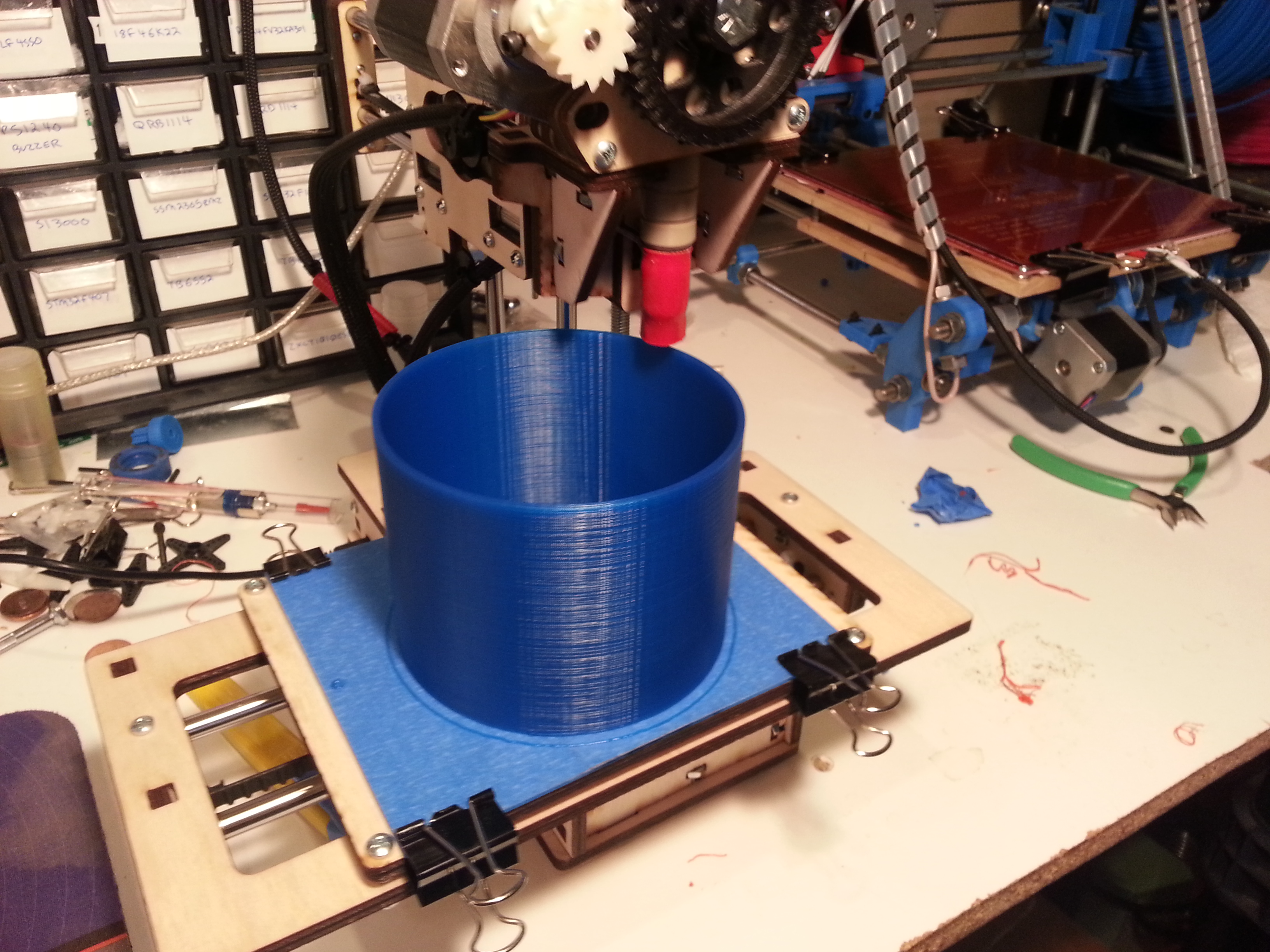
My prusa 3D printer keeps chugging along. Its basically design and print at this point without much messing around. Each different colour that I have needs a little tuning when I first use it but aside that that, its plug and play. One of my sons has started playing chess with his friends at school and wanted a chess set of his own. Perfect thing to do on the 3D printer this weekend.
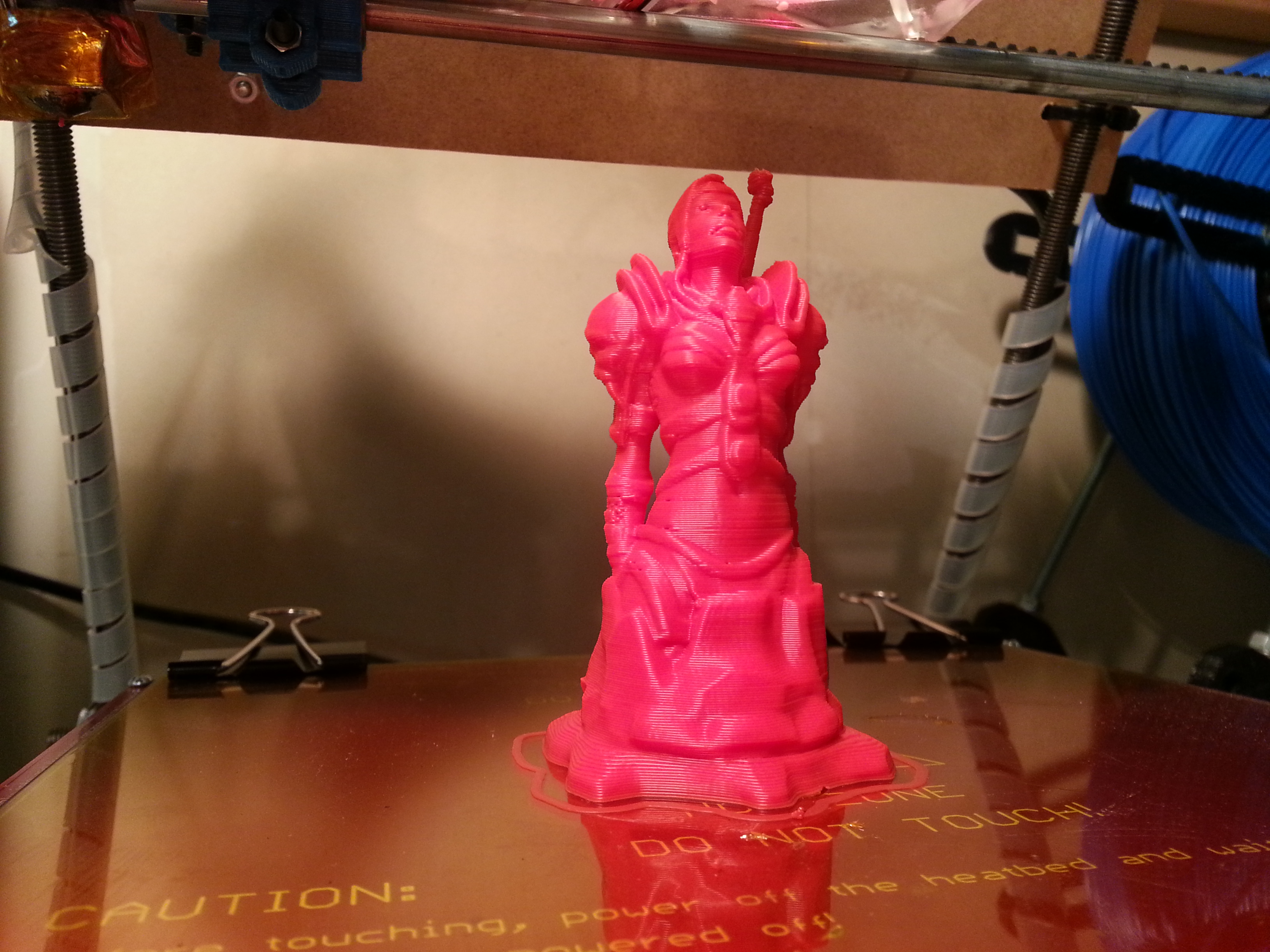
Once that was done, I started looking for something which is a little more distinct. I came across a tiki chess set on Tinkercad by Whystler. Very cool looking but not overly printable. I split the pawn out and printed it to see. Came out pretty nice. The rook prints ok also, but the other models will need a few tweaks to eliminate the overhangs as well as some extra material to beef them up a bit.
I had a Makibox on order for the kids to have their own printer to play with but that project has been stretching on a bit longer than I’d like. I’d guess that they still have quite a few months left so I bailed out for the time being and ordered up a Printrbot Jr. for them instead. Roughly the same build size but limited to PLA only. I think that might end up being the preferred material for them anyhow and not having a heated build plate will make it a little safer for them to use anyhow.
Looking forward to getting our hands on that. Its a very neat looking printer. In fact, it picked up an award at the MakerFaire in New York this past weekend.
Also been doing some PCBs. I tested out the 4-layer PCBs that iTeadstudio has. Its much more expensive ($99 versus $35) but there are times when 4-layers instead of two kicks butt. The design I did (dual motor controller) only needed a portion of the 10cm x 10cm board though and I didn’t want any of that expensive space to go to waste so I panelized 3 other designs onto it. Two of the designs were my own (a STM32 LCD dev board and a STM32 servo controller) and the third was an IMU designed by a co-worker.
Cutting out the panels was a breeze with my Taig CNC. I’m going to start panelizing more of my designs I think.
On the subject of PCBs, I’ve really been wanting some way to get my hands on cheap stencils for spreading out solder paste and then reflowing PCBs. Its so much easier to do. Stencils cost around $50 ($25 + shipping) from Pololu which is ok, but expensive when you are experimenting. It doesn’t take too many of those to end up paying for a cheap 40W Chinese laser. So I took the plunge this weekend and ordered up a K40-III 40W laser. Of course my order coincided with a week long vacation in China, so it likely won’t get shipped out until next week sadly. Hopefully it makes it here in one piece and I don’t have to spend too much time realigning mirrors, etc….
After spending the last couple months tweaking, tuning and generally goofing around with my Prusa Reprap 3D printer, this weekend I figured it was finally time to start printing robot parts.
I’ve had a minisumo design kicking around for the last year or so that was intended to have the lower half cut from aluminum and then some sort of bent sheet metal for the upper portion. The electronics were put together and blogged about on Sept. 27th, 2011. Ouch! July 26th had a shot of the 3D model I was working on for the base.
I printed the original design on Saturday and it turned out pretty good. I still needed the upper part though. And then it hit me… I didn’t have to make it in two pieces any more! I could simply print the entire thing. My brain still works in the 2.5D mode of my CNC machine… with the CNC it always came down to having to fixture the part under design to do undercuts. That is a real pain in the ass… cutting a piece, moving and rotating the work piece, cutting again… and so on. It generally meant that I made the pieces as simple and as 2D as possible.
Well, not any more. I whipped up an initial full 3D design this morning.
Seemed ok. The cavity inside the body is where the LiPo battery sits. The cavity in the back is where the 2 motors sit. There are 4 holes in the case where the sharp IR sensors poke through. They sit under the PCB so I’ve got stand-offs to hold the PCB off as well as bolt down. Initial seat-of-the-pants figuring seemed like the PCB could slip in over the standoffs, drop down and then slip in the rest of the way.
I printed with support material. Essentially it prints with lightly bonded material which can be torn off easily after the job is done. It means that overhangs can be easily printed. It also means that I can treat the design as full 3D as long as I leave room to grab inside and rip out the support material.
So I fired up the printer and headed out for mother’s day supper with the family. When I got back, everything was done. The next 5 pics show what the print looks like with support material still in place.
After about 20 minutes with some pliers and a bit with an exacto knife, the support material was mostly removed and the chassis could finally be seen.
Not too bad at all. Only two little hiccups. In my rush to get out the door for supper, I hurried the warm-up phase on my printer. It takes about 30 minutes for it to stabilize I’ve discovered. The heated bed only takes about 10 minutes to reach temperature but I need to let it sit for another 20 minutes to let all the various bits and pieces physically expand another fraction of a millimeter. If I rush it, I end up printing about 0.05mm higher than expected. For smaller prints it doesn’t matter too much aside from the bottom of the print not being as pretty. As I discovered with this print though, it also means that larger prints have the possibility of pulling off the table and warping. Whoops… Two of the corners of the base pulled up half a millimeter or so. I could likely heat it again and put it back in place, but it was just a test print so it doesn’t bother me much.
The second hiccup was my mounting standoffs. In particular, the ones inside. the sharp sensor could have gotten over as intended, but I forgot that there was a very large capacitor on the PCB right near the front edge. Doh! No way to slip the PCB in with large things on the top and bottom of it.
Ah well… Even if it had been perfect, I still needed to print it again in the right colour and with open areas on the bottom in order to fill it with lead for weight anyhow. It would have been nice to test fit the PCB though. I may cut out the standoffs for a test fit anyways. Another day.
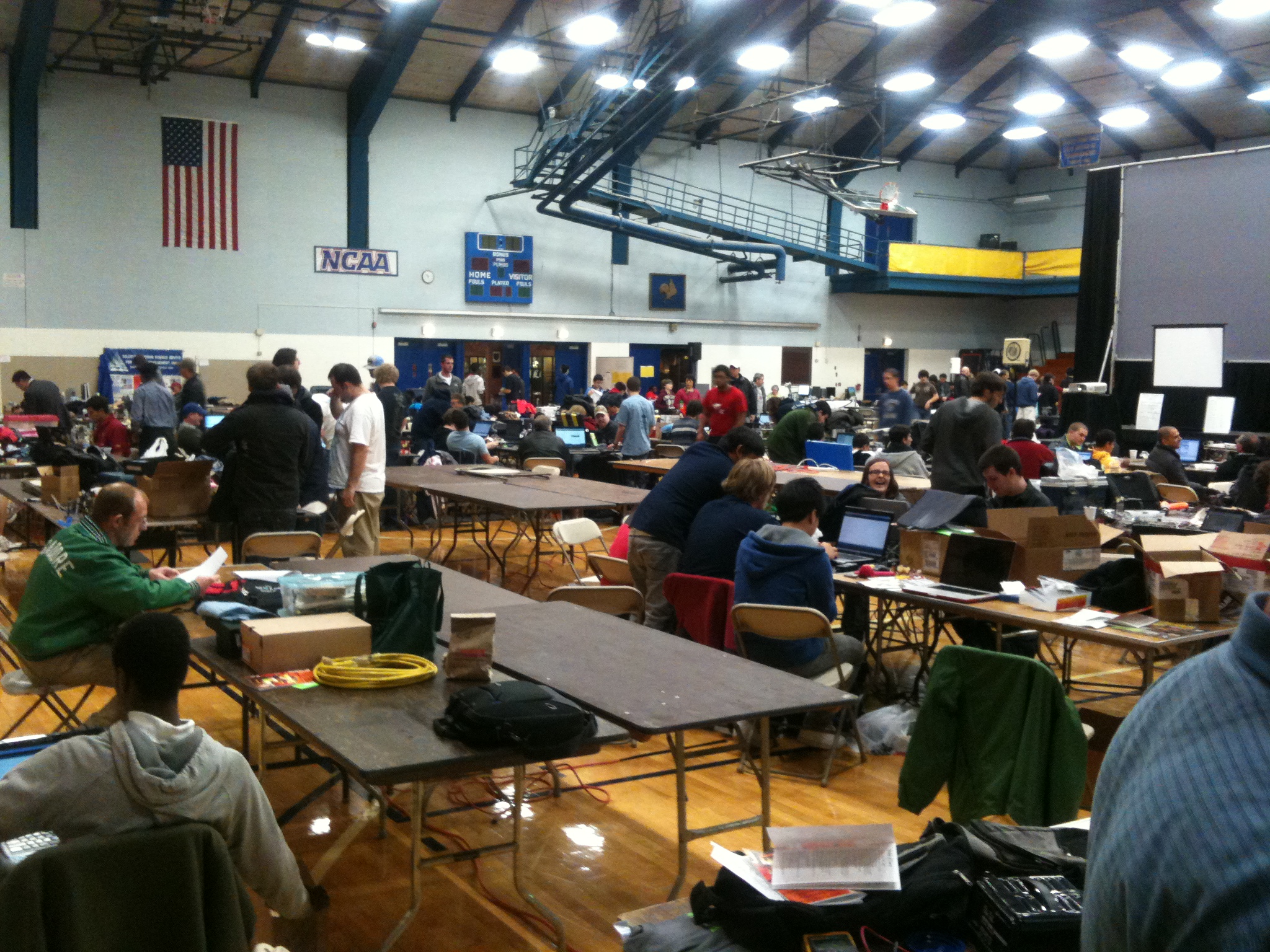
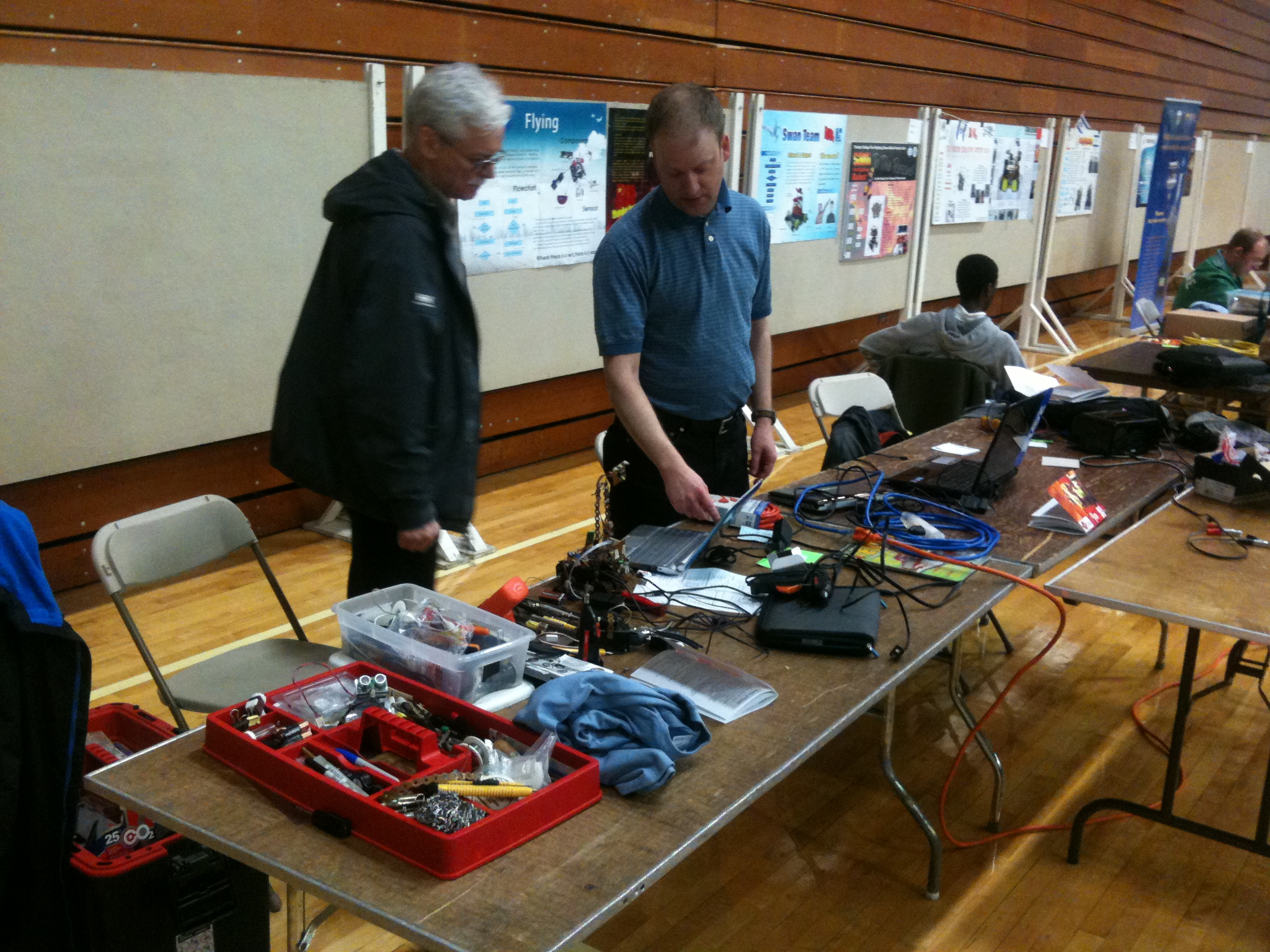
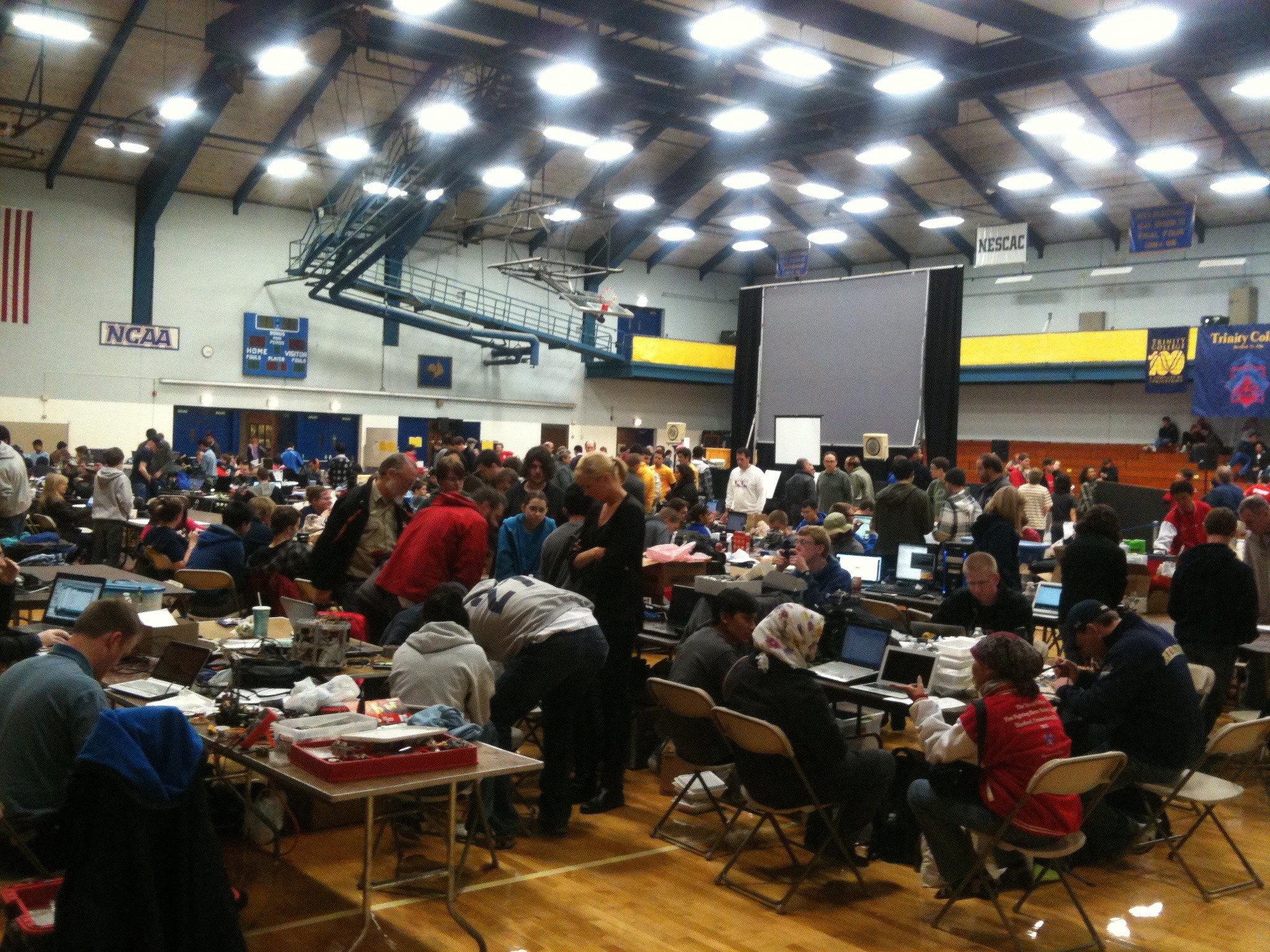
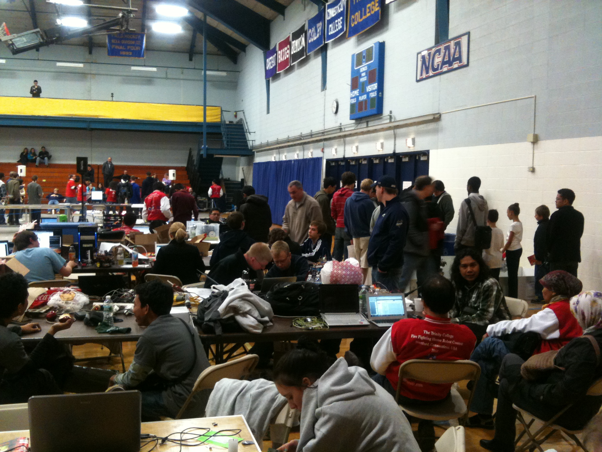
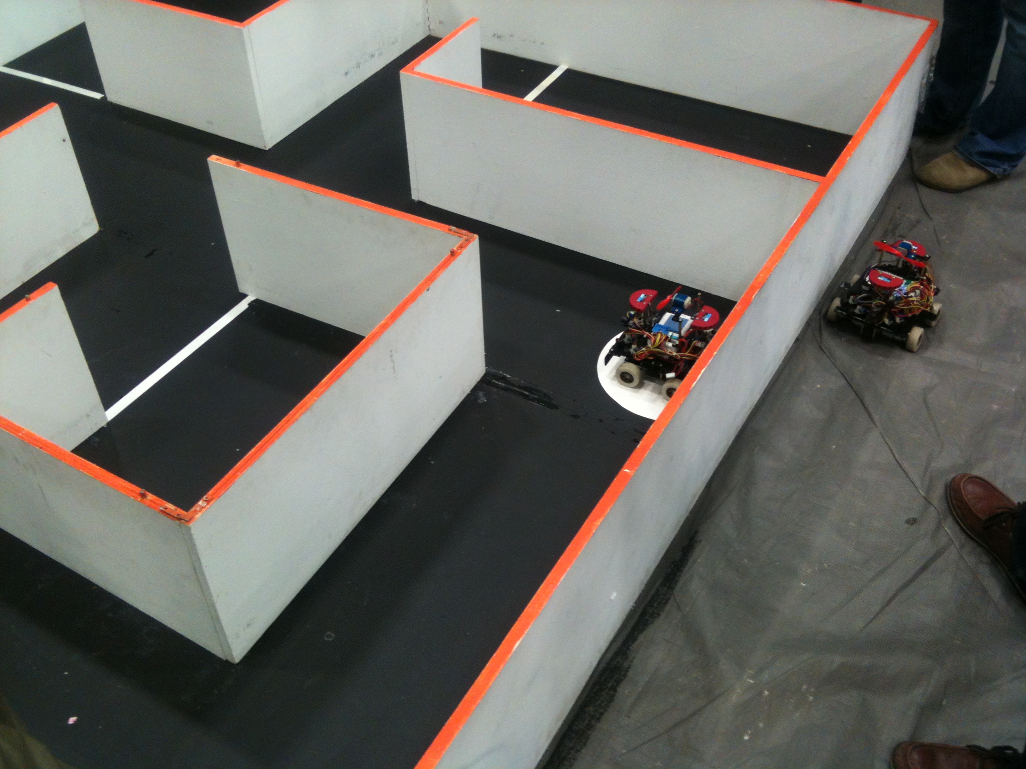
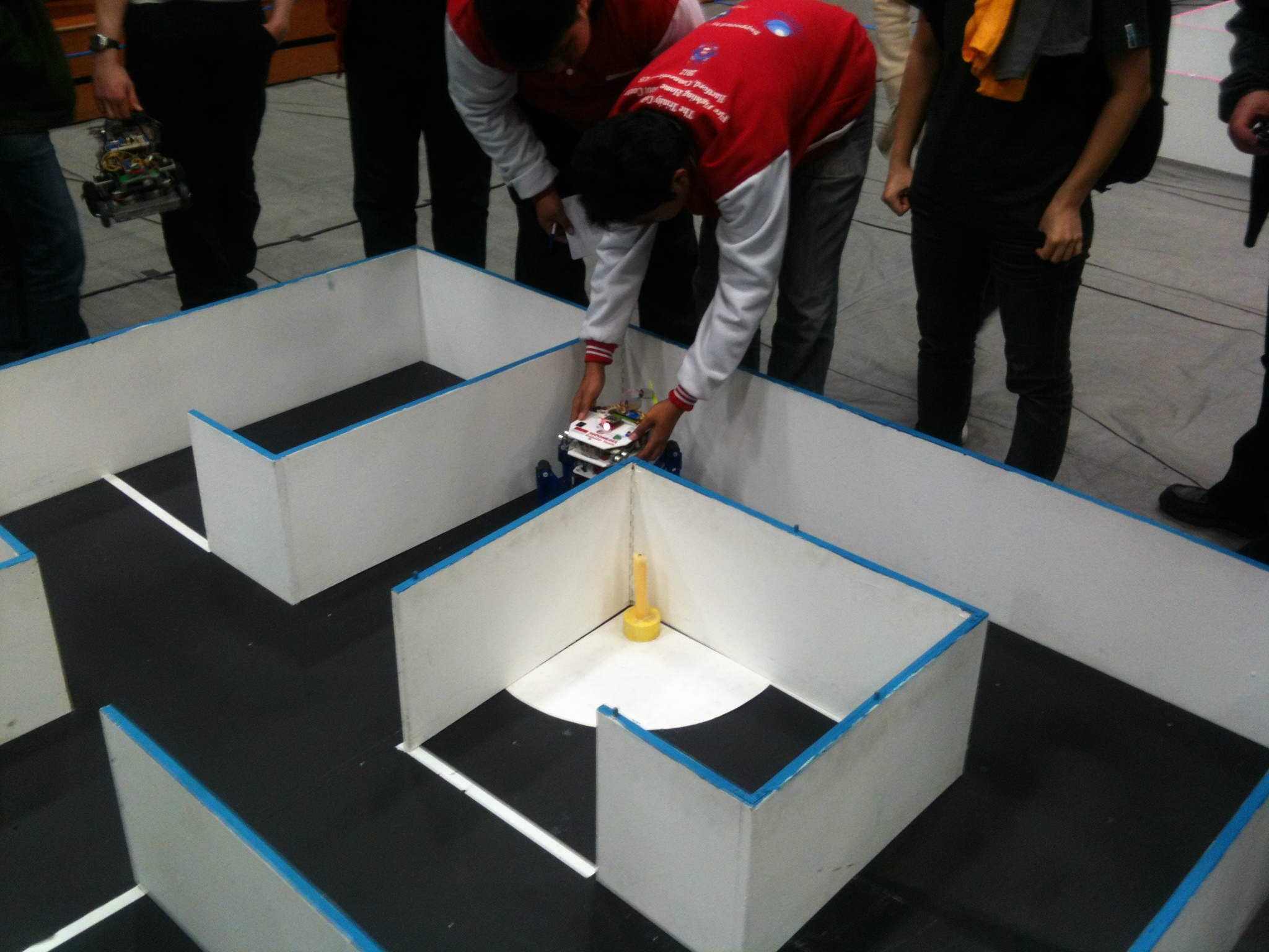
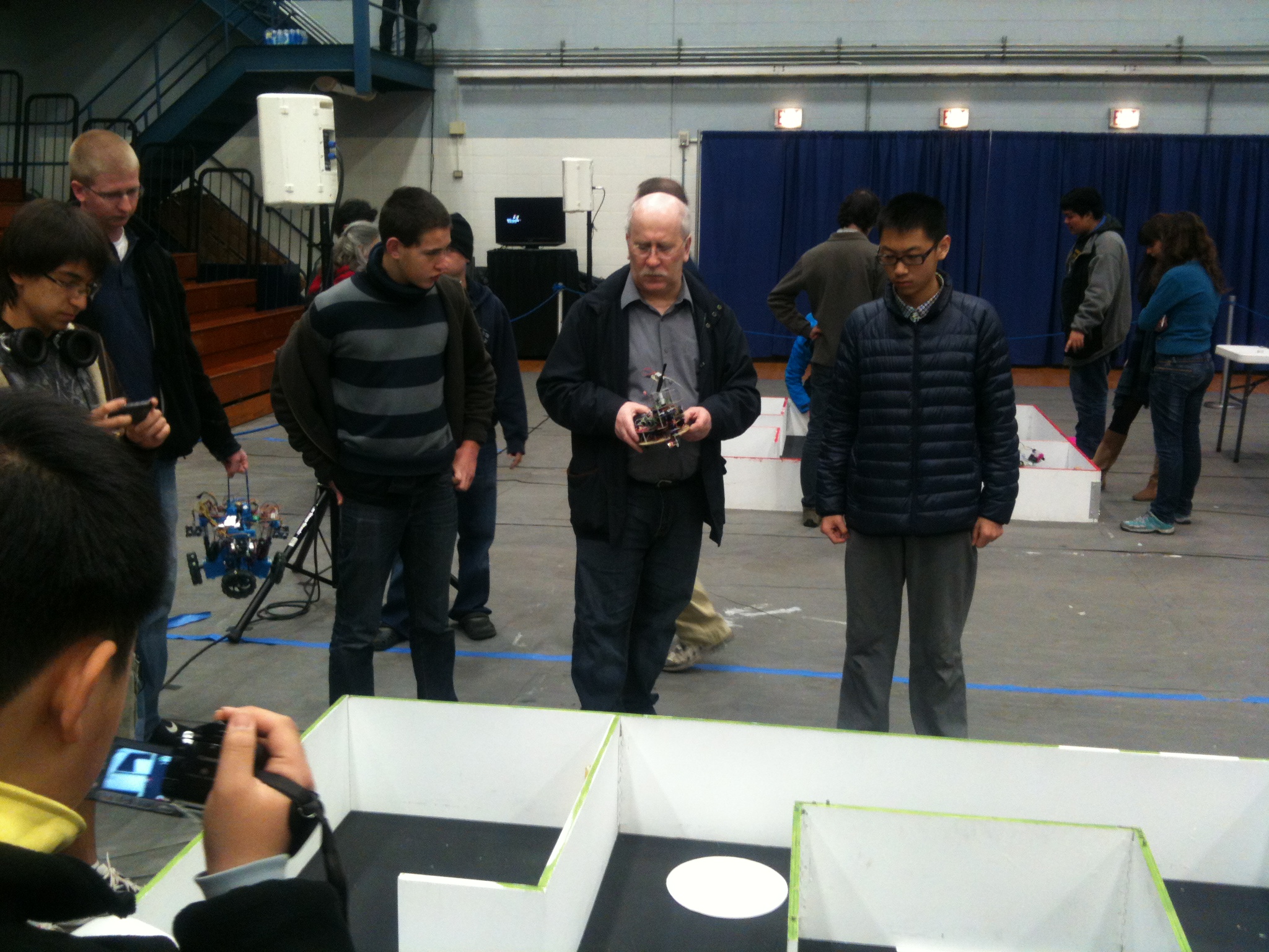
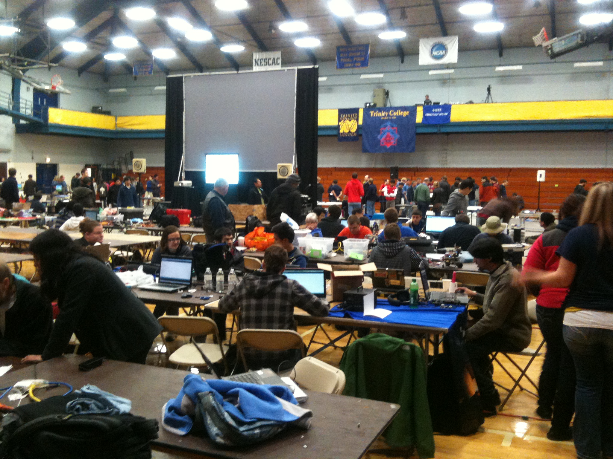
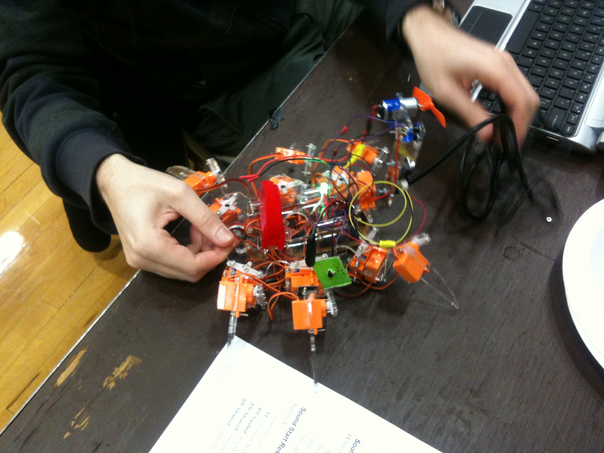
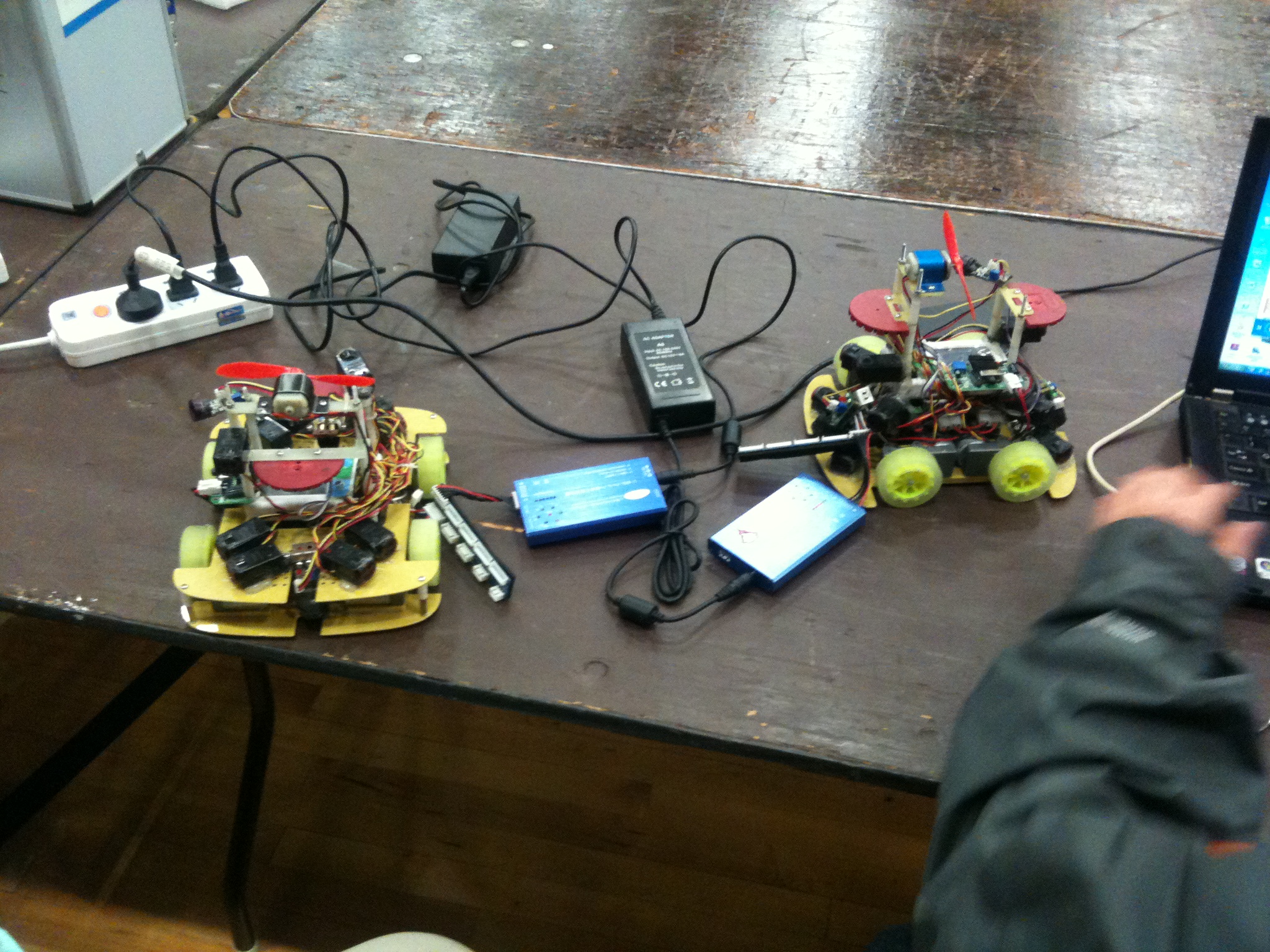
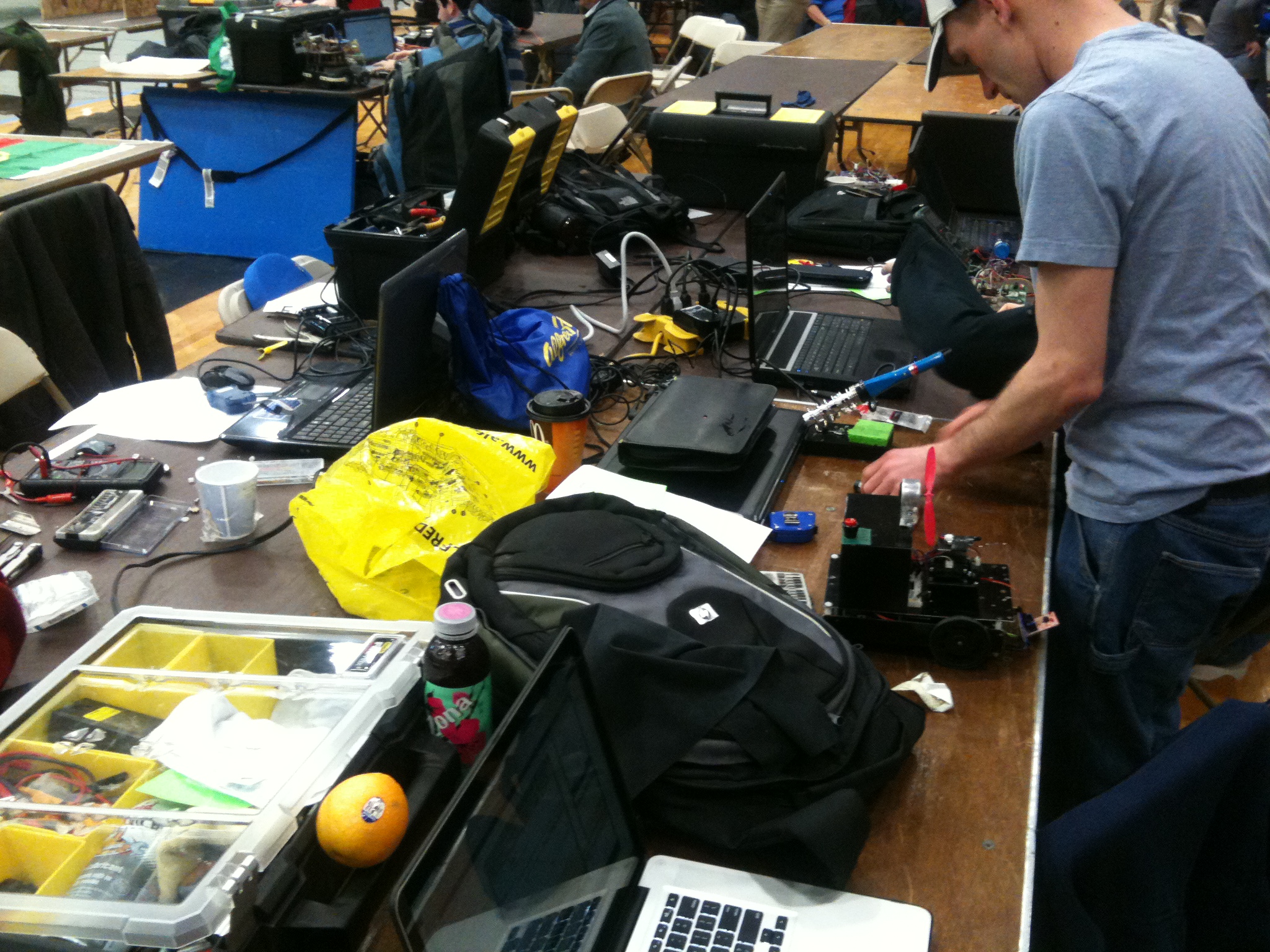
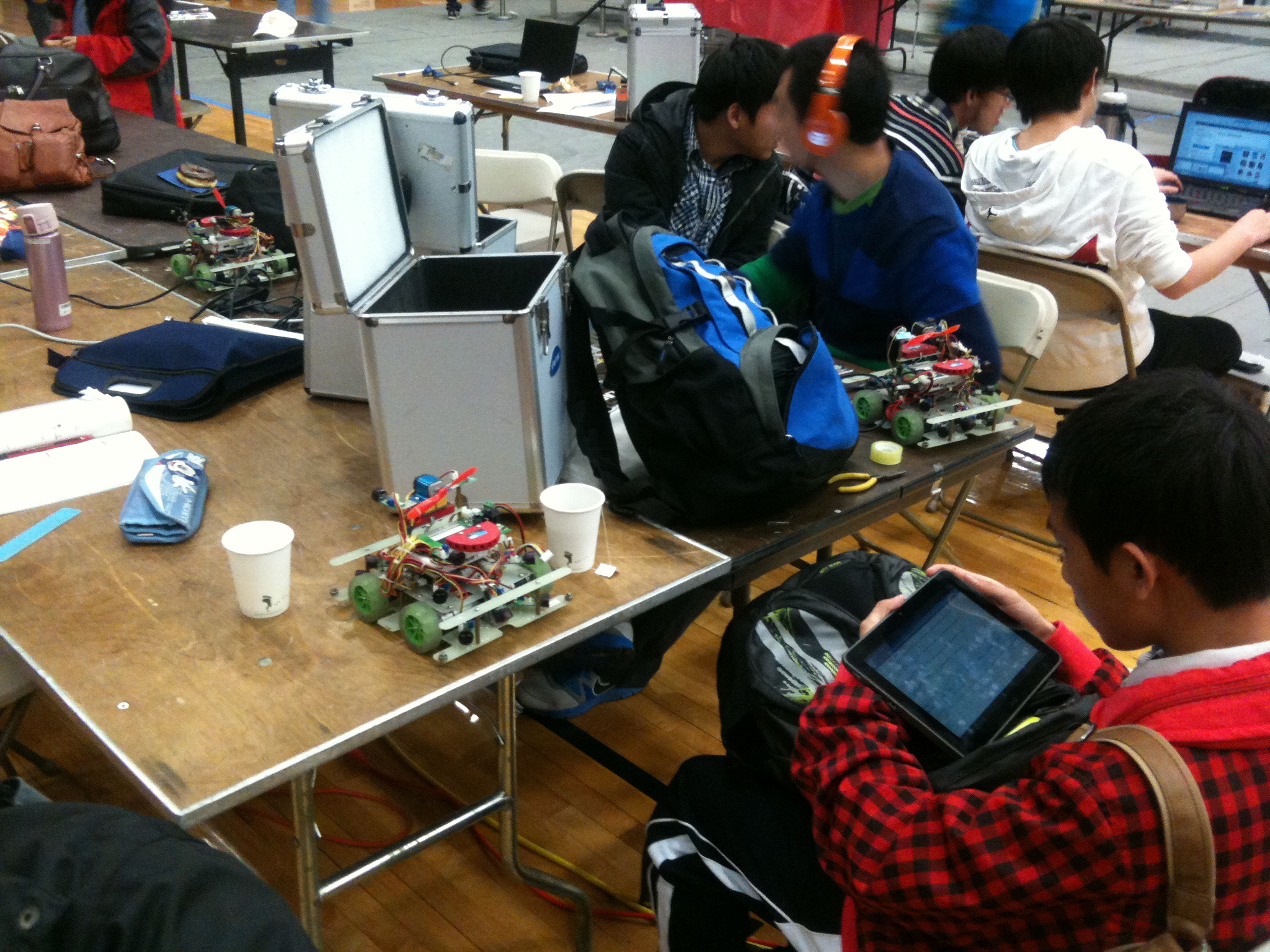
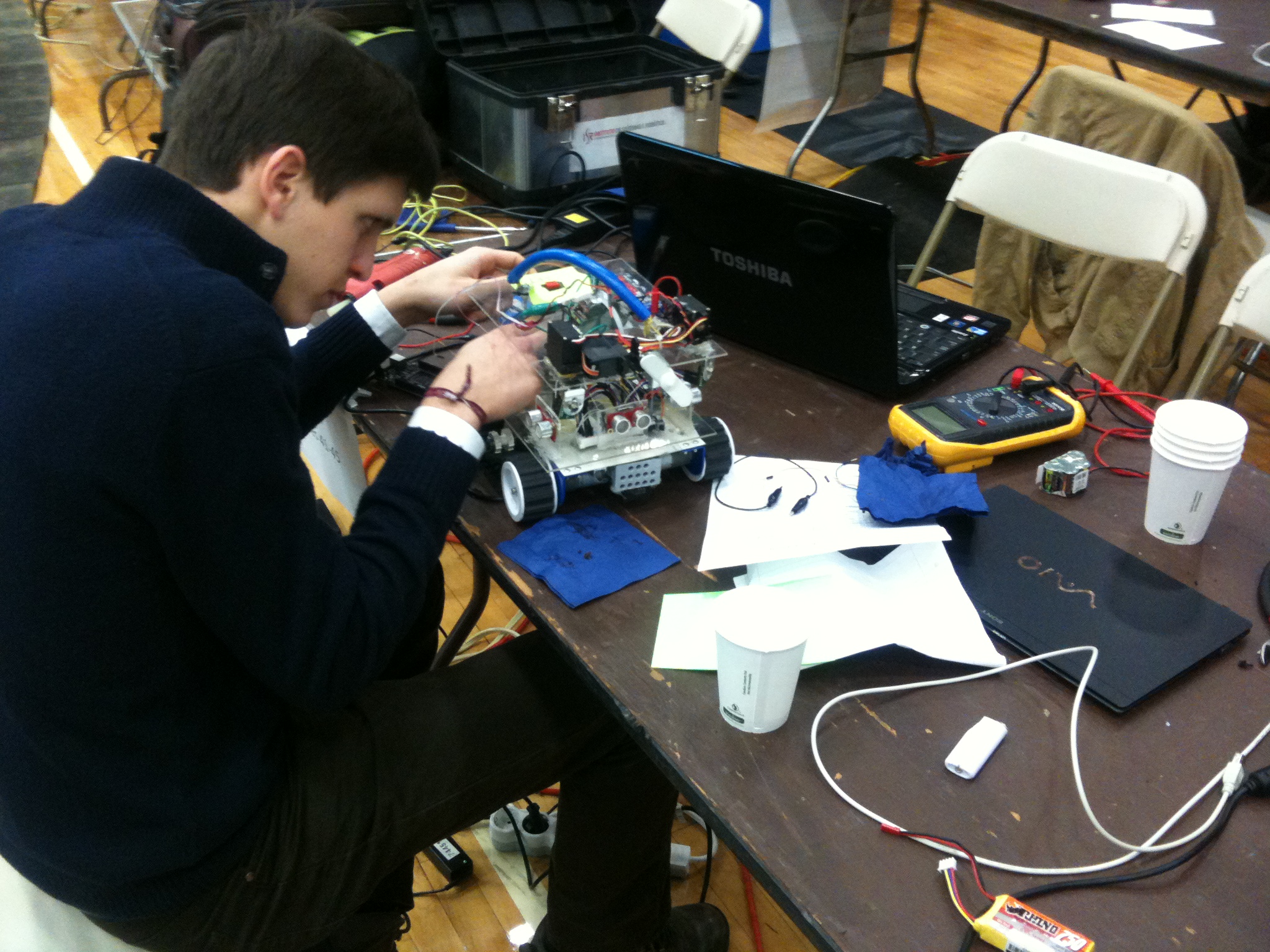
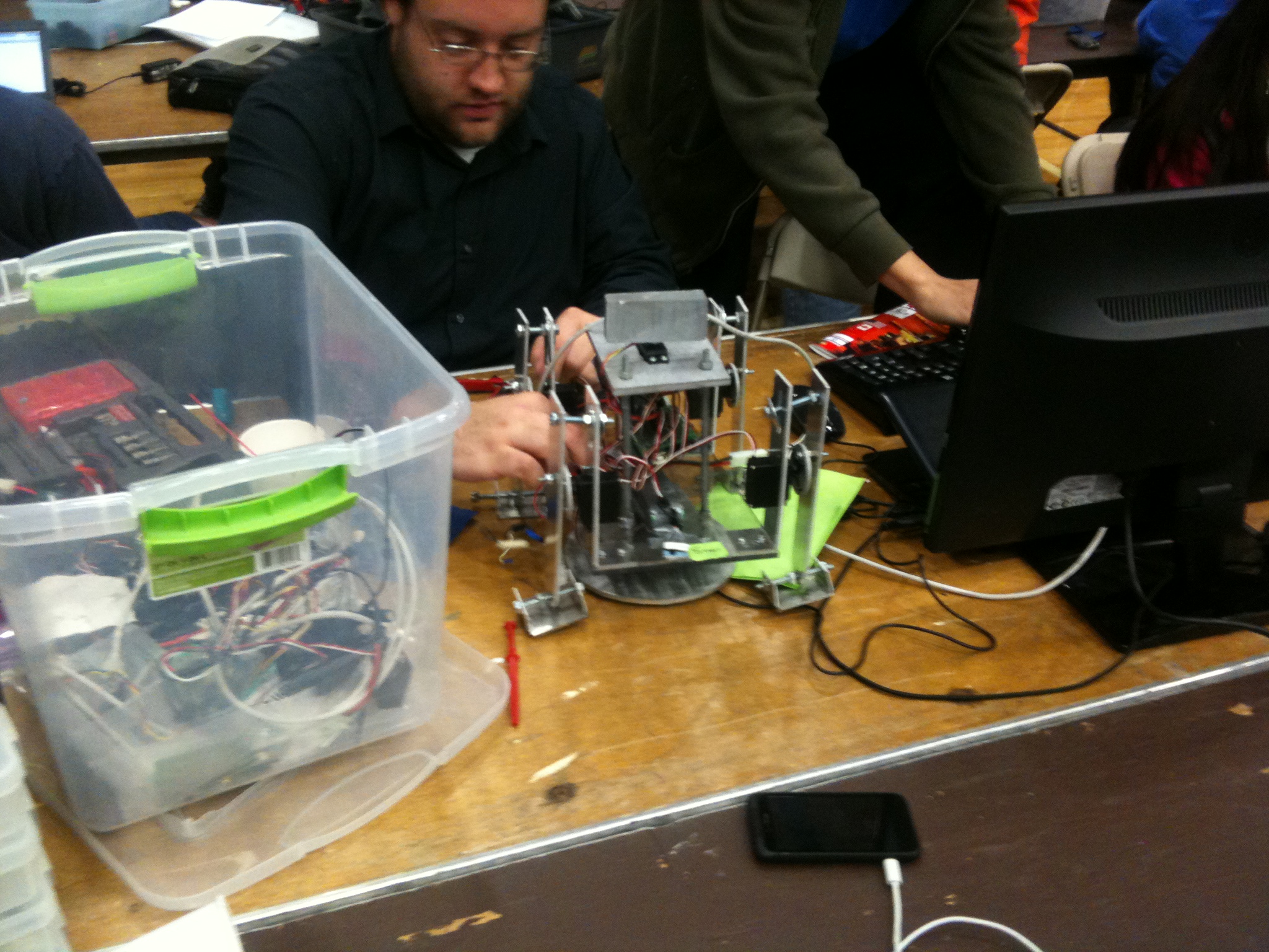
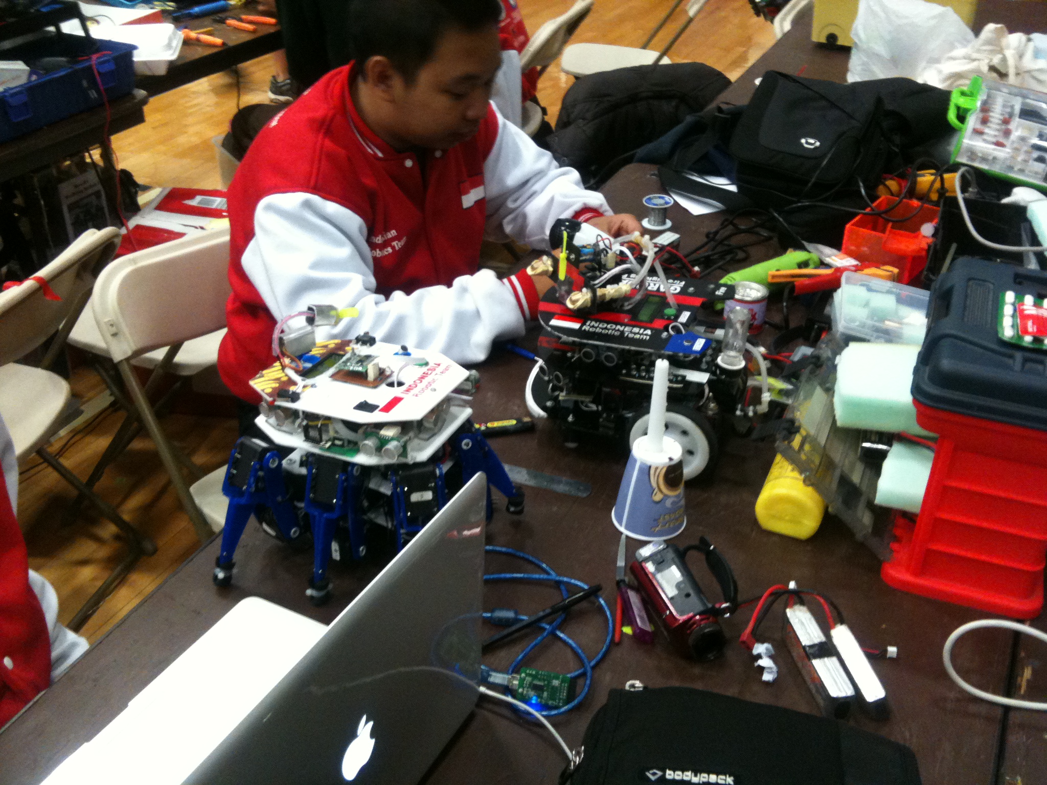
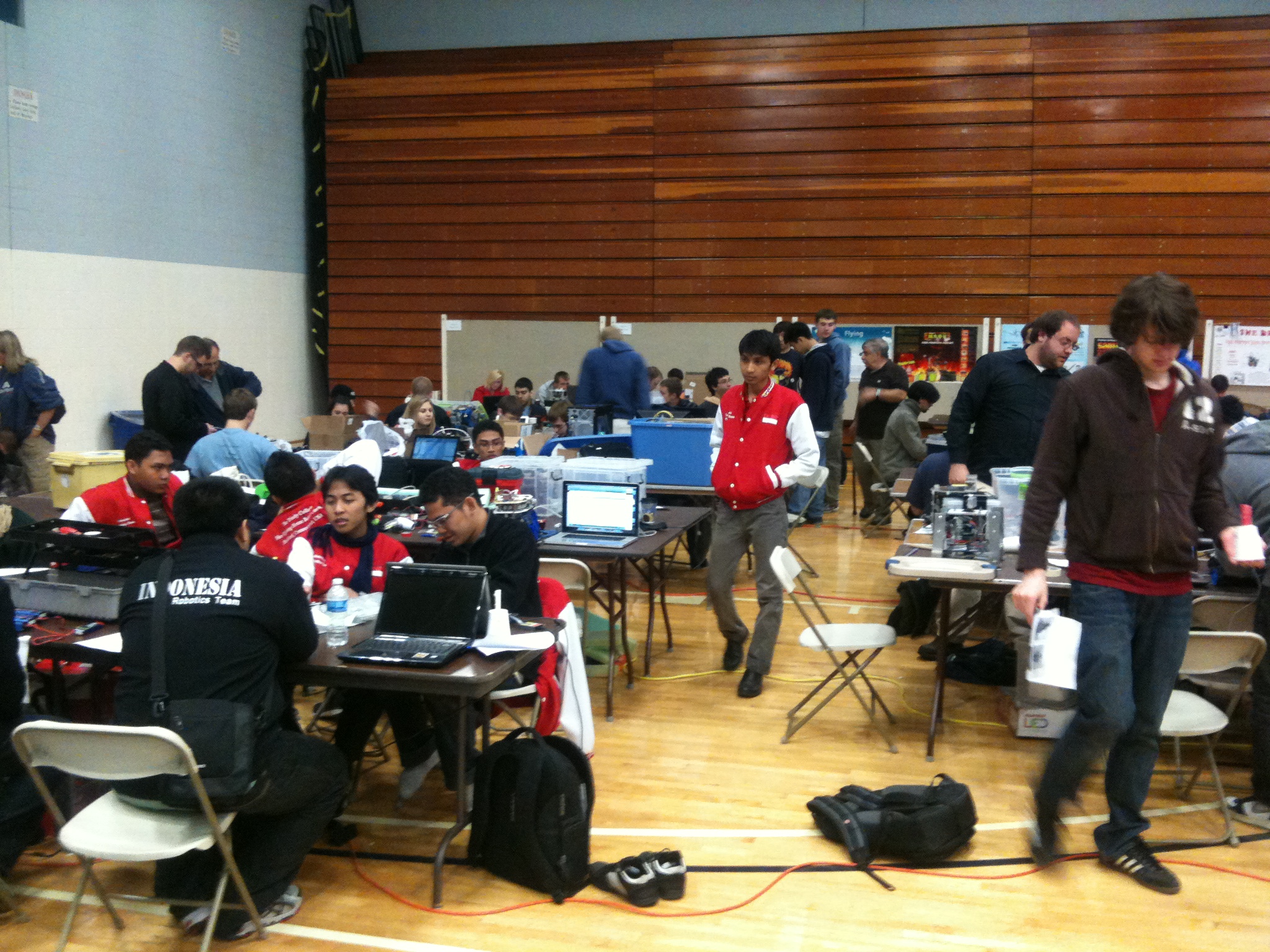
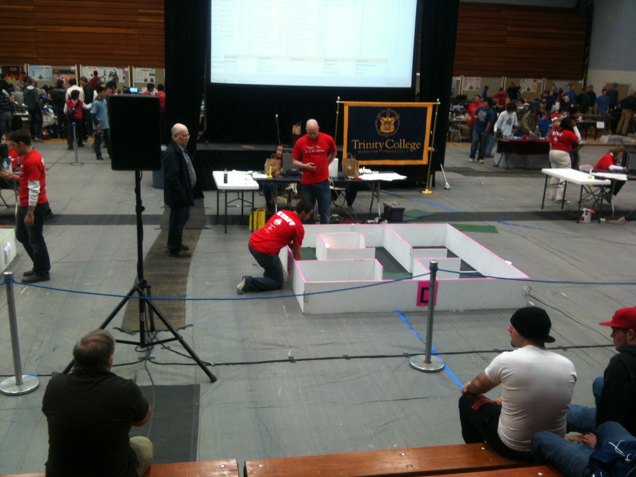
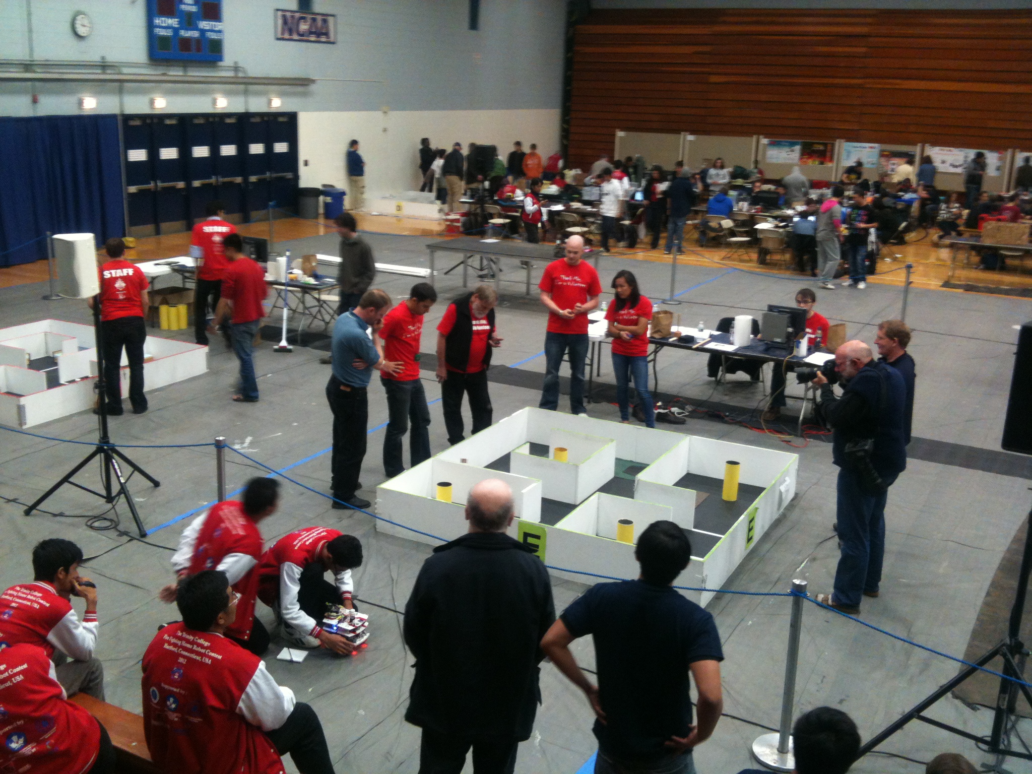
A small group of us from Ottawa made the trek down to Hartford, CT for the firefighting competition. 2 of our members competed. It didn’t go as planned, but I think everyone had fun anyhow. 😉
Anyhow, just a bunch of pictures that I took while we were down there.
I’ll have to get serious for next year and finally bring back a robot to compete!