
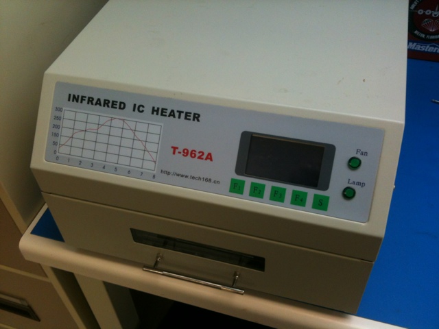
As you may have seen in some of my older posts, I occasionally pull out my Puhui T-962A IR reflow oven for assembling PCBs. We had some small boards at work to put together so rather than farm it out for manufacturing, I proposed building the boards up in-house.
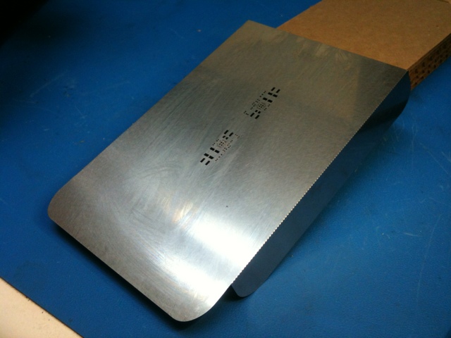
My motive (aside from saving a few bucks) was to try out Stencils Unlimited and see how their quick-turn metal stencils worked. Normally I’ve been using the Pololu mylar stencils for $25, but I’ve always wondered what I was missing out on by not having a nice laser cut metal stencil. The cost is $125, so its a pretty big jump in cost. The metal stencils won’t wear out as easily though and should give a better quality PCB in the end (due to not melting the edges as happens with the mylar).
I opted for the optional stencil kit along with the stencil itself for an extra $20. Turns out that was pretty much a waste of $$$ in my opinion… they include a couple of pieces of PCB material to help hold your PCB in place and have the right height, as well as a thin piece of steel for spreading the solder paste. The PCB holders didn’t do the trick for me as my board is a 1mm thick board instead of the normal 1.57mm and I’ve already got nicer paste spreaders. Ah well… live and learn.
The stencil itself is really nice.
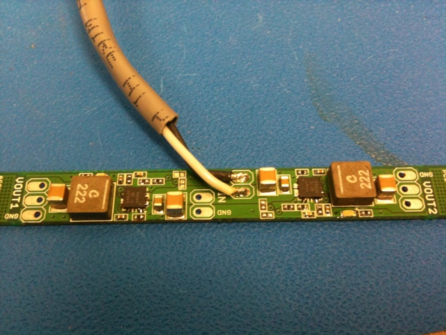
I thought I had it made at this point. Spread the paste and reflowed away. The boards came out looking nice…. but I couldn’t get any response from it. The board is a just simple dual DC/DC converter design using the TI TPS54620. The chip showed some small signs of life but I couldn’t get it to start oscillating and regulate the voltage. I poked and prodded, replaced parts, scoured the datasheet without any success.
So I built up a second PCB. Exact same issue… virtually dead chip. It looked like it was constantly putting itself into reset.
So I started wondering about my reflow machine. I’ve never actually measured the reflow temps inside. I taped a thermocouple to a blank PCB and placed it inside the machine where I had done the previous 2 boards and cycled it. I’m using pre-programmed profile #2 which is intended for leaded solder. It runs a little cooler than lead-free so I prefer it as its easier on the parts.
It turns out that my reflow profile is pretty damn nice. I captured the temp every second and logged it. It matched pretty closely to the temperature that the machine was displaying on its LCD. Plotting the graph shows that the profile is pretty reasonable.

At this point I went a little crazy and re-ran the test but with 4 thermocouples in the machine at different locations to see how well the convection fans inside were working. I had temperatures all within 5C throughout the machine. Pretty damn nice for a $400 (including shipping) unit.
So, no smoking gun yet. So I pulled out my hot-air tool and tore one of the TPS54620 chips off a board and replaced it with a new one by hand. And it worked! Damn. It looks like this chip is particularly sensitive to IR reflow… the material that the device is made from must be absorbing IR and overheating the die inside. So I broke down, and hand assembled the remaining 9 boards. Well… sort of. I reflowed all of the discrete components and only hand-assembled the DC/DC chip itself.
That’s a first for me. The reflow oven has never failed before. I’ll have to experiment with this a little more to see if there is some way to make it work with the TPS54620 device… perhaps some copper tape on top of the part during reflow to keep the direct IR off of it and let the convection heat do the soldering?
2 Responses to IR solder reflow trials and tribulations