The Reprap Prusa 3D printer lives! Finally. ;-)

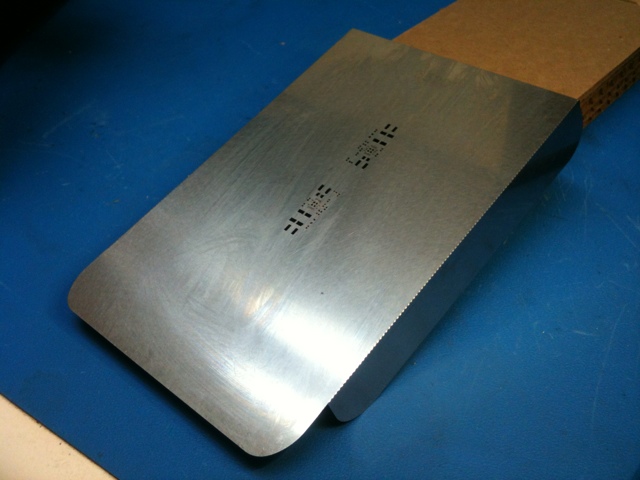
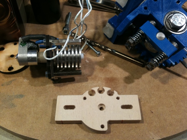
Well, I picked up the pieces for a Prusa 3D printer last year (as documented on this blog somewhere) and quickly built up the frame. I sourced the bits and pieces from all over which meant that some of it wasn’t a bit of a head scratcher to put together. In particular, the hot-end from Arcol was not designed for the carriage that I had. There just wasn’t any way to bolt it together. After pondering it for a while, I ended up cutting out an adapter plate at the end of last summer. That was the last that I worked on it.

I had my doubts about the machine mechanically. It is virtually impossible to get everything aligned. I wanted it to be strong and exact just like my Taig CNC machine, but I just couldn’t get it perfect. So I put it on the shelf and tried to ignore it. It teased me whenever I saw it sitting there all dusty though. I still wanted a 3D printer. And my kids never let me forget that they wanted custom Lego.

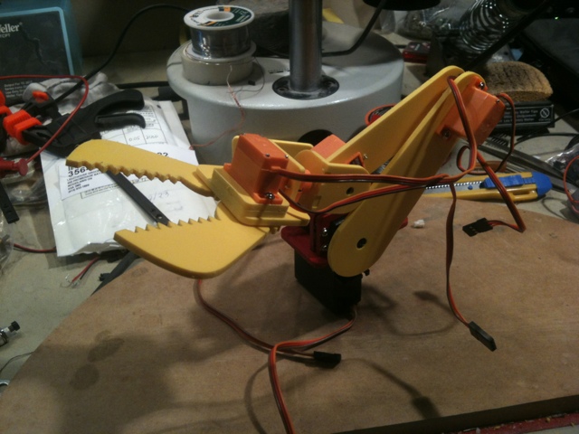
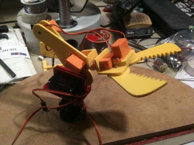
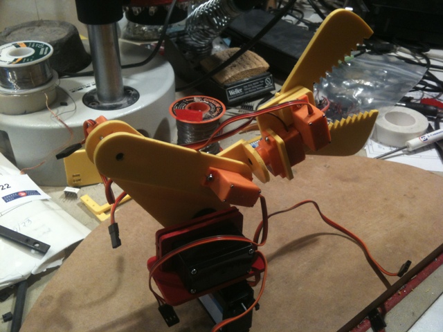
When designing that robot arm back in February it was very apparent that a 3D printer would have made the design much easier than having to stick a bunch of sintra piece together. Around the same time I ran across a 3D printer project called the Makibox. It was in the prototyping stage and being funded through a website called Makible. The form factor was interesting and it looks like aligning it would be much easier mechanically.

Given the interest that my kids had in the machine, the Makibox looked perfect for something that they could use and possibly even be able to bring to school. So I ponied up the $350 for it and sat back to wait.

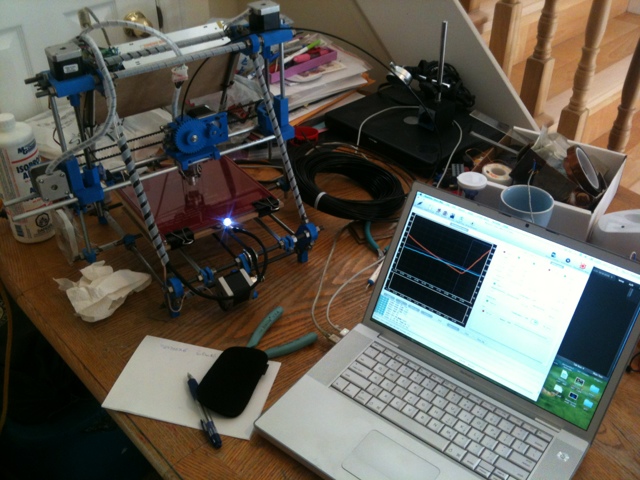
And then the Prusa started to haunt me. How the heck could I justify buying a second printer without having the first one working? So I dug it out and over the last week I finished putting it all together. After a bit of time tweaking, it looks like mechanically close enough on the frame was not a problem really. Once I leveled the bed against the extruder carriage it seems to be good enough. And besides, what is a fraction of a millimeter between friends anyhow. 😉

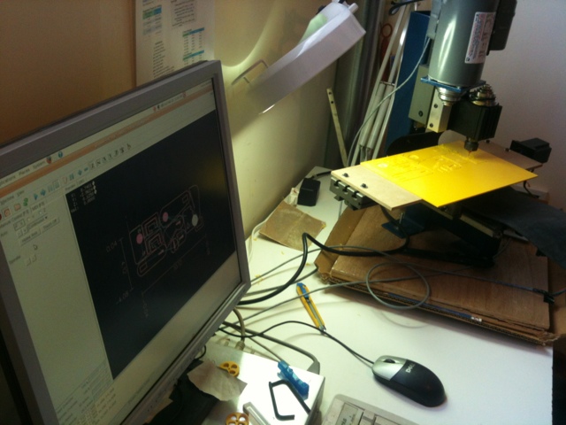
I ran across Repetier for the firmware as well as the interface on the PC. It is frikkin’ awesome. It lets you place your 3D model on your build-plate on the PC, rotate/move/etc.., turns it into gcode, and then print. Aside from the actual 3D modeling, its an all-in-one solution. So much nicer than the alternatives.

Anyhow, finally last night I had everything tweaked and tuned to the point where I could start extruding.

20120312-083907.jpg

After a few aborted attempts of trying to print directly on my heated glass, I ended up covering the glass with kapton tape and got it to print out a shot glass! The tradition is to drink from the first successful print.

20120312-083852.jpg

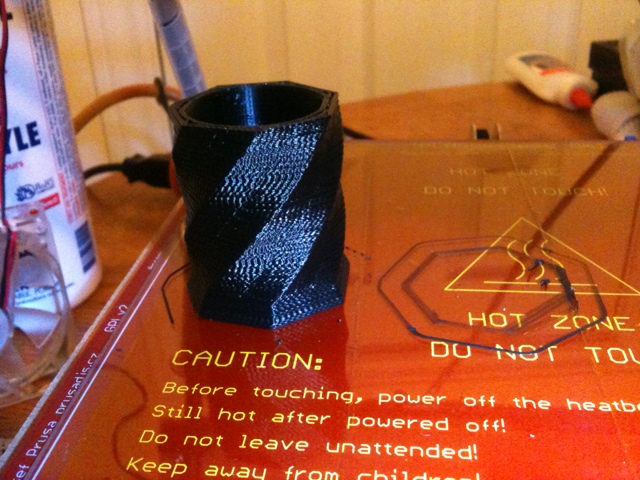
It wasn’t until I had almost finished the print that I noticed the fine print that I should be using an infill of 100% instead of the 40% that I had set it to. 😉 Turns out the bottom of my glass has very small pinholes. Ah well, I drank fast and only spilled about half of it. Success!

Looks like my X axis still has some tweaks to do though. When the carriage moves from left to right there was quite a bit of jitter. I think that it is due to the belt so I’m going to tighten that sucker up and keep on rolling.

Posted in RepRap | 2 Comments

Get a grip

The time has finally come to make a robot arm. Its been on list of things to do since forever. Possibly even longer.

The gripper had me scratching my head a bit. Until I realized that it was pretty dang easy to run one side of the gripper with a servo and have the other side synchronized with a gear.

Whipped a quick drawing in QCad, imported it into CamBam, dumped out the gcode and off to the Taig CNC to cut it out of 3mm sintra.

20120226-181421.jpg

Realized today that I’m still running EMC 2.3.4 from 2008! Wow… Ubuntu 8.04 or something along those lines. Can’t decide if I should bother to upgrade. The machine has been working well so I don’t want to jinx it. Maybe this summer.

20120226-181412.jpg

Not too bad… takes half an 8×12 piece of sintra to cut out the arm. I’m too lazy to cut my own sintra so I buy these sheets from Solarbotics. Likely about twice the price of simply buying a 4×8 sheet of sintra and cutting it down, but getting it in smaller chunks like this means that I can have lots of different colours instead of a crate load of a single colour.

And then off to assemble the arm. I had a bunch of Hobbyking HK15178 and Moxie M38N servos kicking around so I used the 2 larger M38N servos on the base and shoulder joint and 4 of the smaller HK15178 servos everywhere else (elbow, 2x wrist and gripper).

The yellow version shown here is actually the second attempt. The first attempt was close, but I had forgotten to drill holes for the servo horn screws and the mounting holes for the HK15178 servos were too larger. You’ll see in the pictures below that the arm has a red base from the first go… it didn’t change between revs so I left it in rather than switch to yellow.

20120226-181428.jpg

20120226-181435.jpg

20120226-181443.jpg

20120226-181451.jpg

I haven’t powered it up yet. That’s coming this week. The elbow servo may end up having to change to a larger 38g servo instead of the small 9g servo.

Posted in Robot, Servo | 2 Comments

IR solder reflow trials and tribulations

As you may have seen in some of my older posts, I occasionally pull out my Puhui T-962A IR reflow oven for assembling PCBs. We had some small boards at work to put together so rather than farm it out for manufacturing, I proposed building the boards up in-house.

20120224-154739.jpg

My motive (aside from saving a few bucks) was to try out Stencils Unlimited and see how their quick-turn metal stencils worked. Normally I’ve been using the Pololu mylar stencils for $25, but I’ve always wondered what I was missing out on by not having a nice laser cut metal stencil. The cost is $125, so its a pretty big jump in cost. The metal stencils won’t wear out as easily though and should give a better quality PCB in the end (due to not melting the edges as happens with the mylar).

I opted for the optional stencil kit along with the stencil itself for an extra $20. Turns out that was pretty much a waste of $$$ in my opinion… they include a couple of pieces of PCB material to help hold your PCB in place and have the right height, as well as a thin piece of steel for spreading the solder paste. The PCB holders didn’t do the trick for me as my board is a 1mm thick board instead of the normal 1.57mm and I’ve already got nicer paste spreaders. Ah well… live and learn.

The stencil itself is really nice.

20120224-154749.jpg

I thought I had it made at this point. Spread the paste and reflowed away. The boards came out looking nice…. but I couldn’t get any response from it. The board is a just simple dual DC/DC converter design using the TI TPS54620. The chip showed some small signs of life but I couldn’t get it to start oscillating and regulate the voltage. I poked and prodded, replaced parts, scoured the datasheet without any success.

So I built up a second PCB. Exact same issue… virtually dead chip. It looked like it was constantly putting itself into reset.

So I started wondering about my reflow machine. I’ve never actually measured the reflow temps inside. I taped a thermocouple to a blank PCB and placed it inside the machine where I had done the previous 2 boards and cycled it. I’m using pre-programmed profile #2 which is intended for leaded solder. It runs a little cooler than lead-free so I prefer it as its easier on the parts.

It turns out that my reflow profile is pretty damn nice. I captured the temp every second and logged it. It matched pretty closely to the temperature that the machine was displaying on its LCD. Plotting the graph shows that the profile is pretty reasonable.

At this point I went a little crazy and re-ran the test but with 4 thermocouples in the machine at different locations to see how well the convection fans inside were working. I had temperatures all within 5C throughout the machine. Pretty damn nice for a $400 (including shipping) unit.

So, no smoking gun yet. So I pulled out my hot-air tool and tore one of the TPS54620 chips off a board and replaced it with a new one by hand. And it worked! Damn. It looks like this chip is particularly sensitive to IR reflow… the material that the device is made from must be absorbing IR and overheating the die inside. So I broke down, and hand assembled the remaining 9 boards. Well… sort of. I reflowed all of the discrete components and only hand-assembled the DC/DC chip itself.

20120224-160208.jpg

That’s a first for me. The reflow oven has never failed before. I’ll have to experiment with this a little more to see if there is some way to make it work with the TPS54620 device… perhaps some copper tape on top of the part during reflow to keep the direct IR off of it and let the convection heat do the soldering?


Posted in PCB | 2 Comments

New Picaxe40x2 Boards assembled

Spent a bit of time last weekend putting together my new Picaxe40X2 PCBs. I ran into major problems with the PCBs…. the solder simply wouldn’t stick to the pads. I fired off an email to iTeadstudio to see if maybe something had gone wrong in the manufacturing. Amazingly they responded to my emails over the weekend. They figured that perhaps the boards had been mistakenly done with a ROHS HASL process and then not protected well enough during shipping, resulting in the pads being oxidized.  They are going to replace the boards. Nice! I didn’t expect any answers until Monday so I was pretty happy that they responded so quickly and didn’t brush me off. Fantastic customer service. They just became my new favourite place.

In the meantime I struggled along to get one of the boards assembled. I tried rubbing the boards (no luck), lightly sanding the boards (resulting in damaged silkscreen but still not great adhesion of solder to the pads) and finally I broken down and scraped each individual pad with an exacto knife down to the copper before soldering. Ouch! The other boards will be going in the bin while I wait for the new batch to show up.

In the meantime though, I can start working on the software to drive the Nokia LCD. I’ve got a slave 16F1825 processor which will be controlled from the main Picaxe40X2 processor via a serial line. I didn’t want to load up the Picaxe with SPI LCD drivers so a slave processor seemed like the best way to go. I could have used a more simple character LCD but the lure of the full colour screen was too much to resist. 😉


Posted in PCB, PICAXE, Robot | 2 Comments

Knockoff Wii remote for robotics?

Well, I kept seeing super cheap Wii remotes on Ebay. Obviously these things aren’t the real deal, but perhaps they work well enough for some robot projects? I couldn’t resist so I picked up 2 of them for just under $10 a piece. They showed up last week and I finally had a chance to rip them apart. The outside of the remote was amazingly good… From the outside, you’d be hard pressed to see that it wasn’t the real deal.

They even use the tri-wing screws to hold it all together. Once you get inside, the PCB gives it all away though. There is still solder flux in a couple of placed where it was hand-soldered at connectors, the bluetooth section is a module instead of being right on the main PCB and the camera is totally different.


Ah, that camera. Its a shame they don’t use the same one as the real Wii remotes. That was the thing that I really wanted to get out of these things. My hope is to repurpose the IR camera as a flame sensor for a firefighting sensor. 😉 Hard to know if these talk the same protocol as the real Wii remotes though. If they do, it’ll be a cake walk.

After checking it out, I bolted it back together, tossed some batteries in them and handed the two remotes off to the kids to see if they work as well as the real remotes. It seemed as sensitive as the real deal when moving the pointer around the menus and they got a workout in Star Wars Lego just to make sure. They got a big two-thumbs up from the munchkins! That may have been a mistake though handing these things over… the kids don’t want to give them up now.


Posted in Firefighting, Wii | Leave a comment

New PicAxe PCBs arrived

Received some new PCBs today from iTeadStudio. I did these boards using their new colour pcb and 100% test service.

This is the first time I’ve done blue boards with iTeadStudio. They look fantastic. I’m a convert I think… no more red boards for me. 😉

This boards is intended to get my kids and up and running with a reasonably capable all-in-one design based around the Picaxe 40X2. I’ve done a smaller PicAxe board in the past around the 28X2 but this time I wanted to really max it all out. The board a dual 3A h-bridge, built in programmer/debugger, d-class audio amplifier, nokia 192×192 graphic LCD, slave PIC processor, 25 I/O ports, 2 regulators, as well as a bunch of buttons, leds and whatever else I could think up at the time.

Schematics in PDF format

It was also my first foray away from Eagle for my personal stuff. After test driving a bunch of other tools, I’ve decided to move to Diptrace. Its an amazing layout program, as well as bundles cheaper than Eagle. With version 6 of Eagle coming out, I was looking at a $550 upgrade charge to move to the new version. Perfect time to jump ship. 😉

Schematics in DipTrace format

PCB layout in DipTrace format

The Freescale MC33932 that I’m using on this board (as well as a few others) has a big old heatsink on the bottom of it so its easier to run the PCB and chip in my reflow oven. The trick is the the MC33932 chips are MSL3 (moisture sensitivity level 3). Once you open the package, you’ve only got 168 hours to reflow the chips before they absorb so much moisture that they are likely to crack during the temperature profile of reflow. I hate MSL3 parts. Anyhow, once you open that package you are committed. So I ended up running a batch of 19 boards tonight, putting this chip on the Picaxe design as well as a firefighter design that also uses the chip.

Weeeeeeeeee! I don’t need all those boards but no sense wasting the h-bridge chip.


Posted in PCB, PICAXE, Robot | 2 Comments

Who says LiPo batteries are dangerous?

Had a bit of fun with some LiPo batteries today. I had an opportunity to purposely burn up some LiPo cells today to see if a simply aluminum enclosure can contain the heat generated when they let loose.

Serene scene before

Pretty box before the LiPo destruction

I had 4 Turnigy nano-tech 4400mah 7S Batteries in the box, connected to create a single 8800mah 14S pack. Starting with the cells fully charged, I pushed 4 amps of current into them for a little over an hour before they finally gave up. It hit 72 volts right before everything went wrong with the cells. Impressive to say the least… my money was on them failing much sooner. Temperature inside the enclosure went over 1370 degrees Celsius (the limit of my data logger) for a few seconds before settling down to 900 degrees for 5 or 6 minutes. It took about 30 minutes for it finally the cool down to 400C. The cell closest to the camera looks like it blew first and hardest… it managed to blow a penny sized hole in the aluminum at some point. That side of the enclosure was bent and cracked from the heat also.

The initial smoke is caused by the first cell letting go. The second blast which hits the camera is the other three cells from what I can see. The next test will be with 8 cells and a stronger box. 😉

LiPo Burn Aftermath

LiPo Burn Aftermath

Poor LiPo cells...

Remnants of $500 worth of LiPo cells


Posted in LiPo | 5 Comments

Cancellation of CNRG hits the news

Wow, this was a bit unexpected. I was pinged by Ashley Burke from the CBC about a piece on the cancellation of the Canadian National Robot Games (CNRG) on Thursday last week. Early Friday I did a quick interview with her for the radio and they also had a phone interview with Steve Jones, the president of the CNRG games. That piece ran early Saturday morning on CBC Radio (of which only the sound bites from Steve made it through I think).

To add to the fun, we (2 of the kids and me) also got to do a live interview just before 6pm on Friday with Alan Neal on All In A Day. Very cool… I’m a big CBC fan and I listen to Alan every day. The kids were excited but a little intimidated when I slipped up and let them know that lots of people might be listening. 😉

The MP3 of that interview can be listened to here : http://www.aaronramsey.com/public/CBC_11nov2011/all_in_a_day_interview_11nov2011.mp3

Early Saturday the interview with me ended up on the CBC website here : http://www.cbc.ca/news/canada/ottawa/story/2011/11/11/ottawa-robot-competition-cancelled.html

The various comments on the CBC page are good for a chuckle. That story was retweeted and picked up by a couple other places, including :

http://ottawa.openfile.ca/blog/curator-blog/curated-news/2011/stay-strong-ottawa-robot-enthusiasts

http://www.upi.com/Science_News/2011/11/12/Canadian-robots-competition-canceled/UPI-63681321147468/

http://www.spacedaily.com/reports/Canadian_robots_competition_canceled_999.html

http://thegrumpyowl.com/2011/11/13/national-robot-games-cancelled/

The post by Travis Boisvenue on OpenFile has an awesome pic. And I love the comment on Ryan Oakley on TheGrumpyOwl.com about kids and broccoli. And the pic by saddamoil is amazing. Perfect for the games being cancelled.

Managed to make it to Reddit also. Not exactly front page material though. 😉

Anyways, that made for a fun weekend. The good news is that we’ll be running the Eastern Canadian Robot Games (ECRG) here in Ottawa on May 12th, 2012 to fill the gap. Details to follow.

In other news, the fam and I hit 100 consecutive days of geocaching this saturday (Nov 12th). Not sure if we can keep it up for another 265 days to make it a full year or not. Got my fingers crossed.

See everyone at the O.R.E. meeting on November 14th!

Posted in CNRG, MiniSumo, Robot, Robot Games | 2 Comments

Starting to put stuff together for CNRG

Starting to put my new minisumo and firefighter designs together.

I put together a small flame sensor using IR phototransistors. I’ll need to either print or CNC a lid for it. The idea is that the 11 sensors give a nice location of where the flame is, so it will be fast. The Chinese team at the Hartford firefighting competition use something similar. The sensor will be standalone and readable via I2C.

20110926-081829.jpg

20110926-081854.jpg

The minisumo design is one that I started for the 2010 CNRG Robot games in Toronto but didn’t get the chassis design ready in time last year. It is similar to my 4 wheel buttercup design but with only 2 wheels. It will be a little taller but should be as fast and strong. The idea is quickly detecting the enemy and hitting them as hard and fast as possible.

20110926-081905.jpg

20110926-081915.jpg

My new firefighter brain board had a major pinout error on the new h-bridge so I had to reorder it from Seeedstudio. Whoops! I had new linefollower and sumoORE pcbs to run at the same time so it wasn’t too bad, aside from losing a few weeks of coding time. Hopefully I will see those new week!

Posted in CNRG, Firefighting, MiniSumo, PCB, Robot, Robot Games | 5 Comments

Finally back working on the Reprap

After sitting on the backburner for most of the summer, it was time to get back to my Prusa Mendel Reprap build. It stalled when I went to mount my Arcol hotend to the chassis…. I needed to build a mounting bracket to make it all fit together. Whoops! Arcol didn’t mention that. 😉 I couldn’t find any info on what sort of mount was commonly used but I did find a picture and STL for a mount for the BudaSchnozzle which is a clone. The STL files didn’t help much as they require a working printer to make the bracket…. Catch-22.

Anyhow, I headed out on vacation with the intent of working on it later. Later finally came.

I drew up an adapter in QCad, turned it into geode in CamBam, and finally cut it from 6mm plywood. Looks good.

20110908-082628.jpg

As I went to mount it, realized I need different length bolts than were included with the Arcol, now that I’ve changed the top plate. Doh! Off to the hardware store.

Posted in RepRap | Leave a comment